1 / 106Use ← → to flip
Machinery and Machine Guarding Hazards for General Industry
Machinery and machine guarding hazards for general industry from the New Jersey State AFL-CIO.
Slide text
· 106 slides · by New Jersey State AFL-CIO, Community Services Agency
The words on each slide as the author wrote them, read from the file by software so they can be searched. Layout, pictures and tables are not shown here: the slides above and the download are the original.
- Slide 1
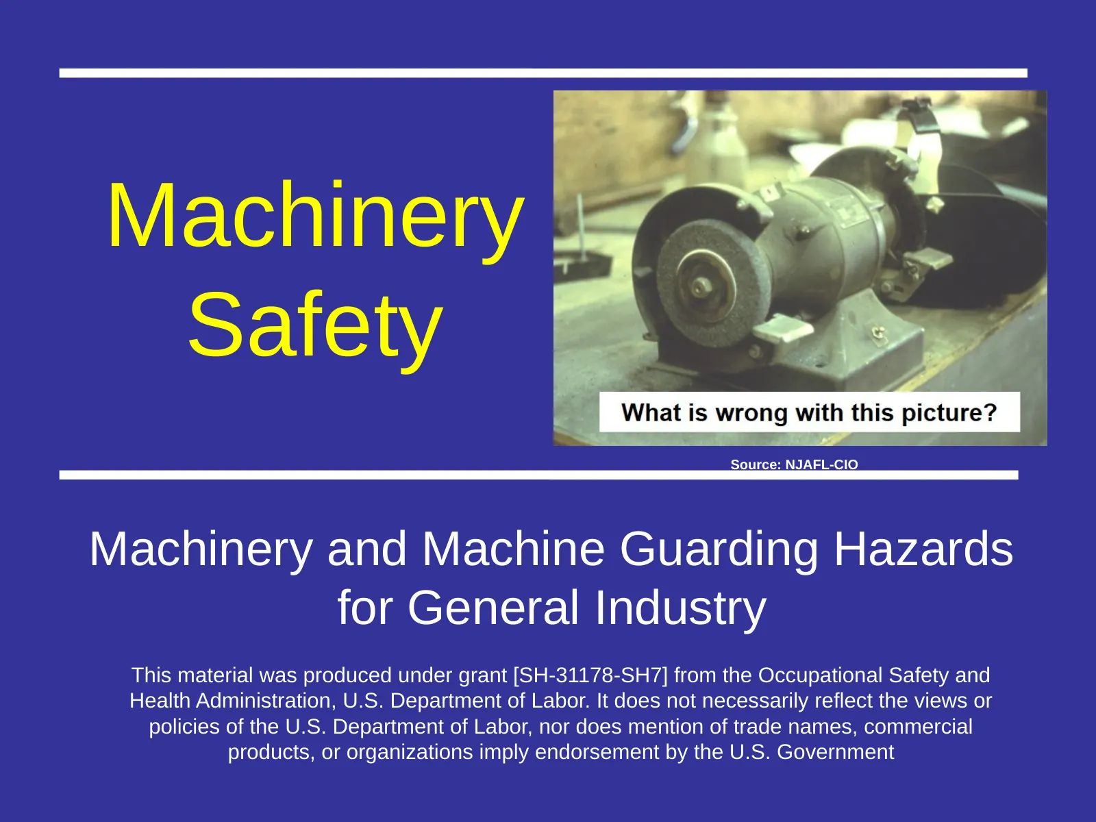
Machinery Safety
- Source: NJAFL-CIO
- Machinery and Machine Guarding Hazards for General Industry
- This material was produced under grant [SH-31178-SH7] from the Occupational Safety and Health Administration, U.S. Department of Labor. It does not necessarily reflect the views or policies of the U.S. Department of Labor, nor does mention of trade names, commercial products, or organizations imply endorsement by the U.S. Government
- Slide 2
Machinery Safety Training
- Group Worksheet or Discussion
- Slide 3
The Problem
- Speaker Notes: Machines are fixed and portable powered devices that do work tasks. They have moving parts that can cause worker injury.
- Data source - https://www.osha.gov/SLTC/etools/machineguarding/index.html
- Source of picture: OSHA 7100 Curriculum Student Manual
- Machines have the potential to cause
- Crushed fingers or hands
- Amputations
- Burns
- Blindness
- Fatalities
- Source: OSHA
- Each year machinery workers suffer approximately
- 18,000 amputations, lacerations, crushing injuries, and abrasions
- 800 deaths
- Slide 4
High-Risk Machinery
- Speaker Notes: Data Source – OSHA Quick Card – Amputations
- (https://www.osha.gov/Publications/amputations-qc.html)
- 1. Mechanical power presses
- 2. Power press brakes
- 3. Powered and non-powered conveyors
- 4. Printing presses
- 5. Roll-forming and roll-bending machines
- 6. Shearing machines
- 7. Food slicers
- 8. Meat grinders
- 9. Meat-cutting band saws
- 10. Drill presses
- 11. Milling machines
- 12. Shears, grinders, and slitters
- 13. Table and portable saws
- Slide 5
Causes of Machine Incidents
- Reaching in to “clear” powered equipment
- Performing maintenance on powered equipment
- Unauthorized person doing maintenance or using the machine
- Missing or loose machine guards
- Lack of worker training
- Slide 6
Prevention
- Speaker Notes: 1910.212(a) Machine guarding.
- 1910.212(a)(1) Types of guarding. One or more methods of machine guarding shall be provided to protect the operator and other employees in the machine area from hazards such as those created by point of operation, ingoing nip points, rotating parts, flying chips and sparks. Examples of guarding methods are-barrier guards, two-hand tripping devices, electronic safety devices, etc.
- 1910.212(a)(2) General requirements for machine guards. Guards shall be affixed to the machine where possible and secured elsewhere if for any reason attachment to the machine is not possible. The guard shall be such that it does not offer an accident hazard in itself.
- 1910.212(a)(3) Point of operation guarding.
- 1910.212(a)(3)(i) Point of operation is the area on a machine where work is actually performed upon the material being processed.
- 1910.212(a)(3)(ii) The point of operation of machines whose operation exposes an employee to injury, shall be guarded. The guarding device shall be in conformity with any appropriate standards therefor, or, in the absence of applicable specific standards, shall be so designed and constructed as to prevent the operator from having any part of his body in the danger zone during the operating cycle.
- Safeguarding any machine part, function, or process which may cause injury
- Controlling or eliminating all hazards where the operation of a machine can injure the operator or other workers
- Training workers on the hazards of machines and how to safely operate and
- repair machinery
- Slide 7
Applicable OSHA Standards
- Speaker Notes:
- There are numerous OSHA standards that cover machinery safety. This is list of the General Industry standards:
- 1910 Subpart J: General environmental controls
- 1910.147 - The control of hazardous energy (lockout/tagout)
- 1910 Subpart O, Machinery and machine guarding. Includes definitions, general requirements, and different kinds of machinery requirements
- 1910.211, Definitions
- 1910.212, General requirements for all machines
- 1910.213, Woodworking machinery requirements
- 1910.214, Cooperage machinery [Reserved]
- 1910.215, Abrasive wheel machinery
- 1910.216, Mills and calendars in the rubber and plastics industries
- 1910.217, Mechanical power presses. Includes general requirements in addition to specific requirements for construction, safeguarding, dies, inspection, maintenance, modification, operation, injury reporting, and presence sensing device initiation (PSDI).
- 1910.218, Forging machines
- 1910.219, Mechanical power-transmission apparatus
- 1910 Subpart P - Hand and Portable Powered Tools and Other Hand-Held Equipment
- 1910.241 - Definitions.
- 1910.243 - Guarding of portable powered tools.
- 1910 Subpart R, Special industries
- 1910.262, Textiles. Paragraph (c)(3) [reserved] contains a short statement on machine guarding requirements and a reference to 29 CFR 1910.219. [related topic page]
- 1910.263, Bakery equipment. Paragraph (c) addresses general requirements for machine guarding.
- 1910.268, Telecommunications. Paragraph (b)(1)(v) addresses some general requirements for machine guarding.
- 29 CFR Part 1910
- Subpart J (1910.147): The control of hazardous energy (Lockout/Tagout)
- Subpart O: Machinery and machine guarding
- Subpart P (1910.243): Guarding of portable powered tools
- Subpart R: Special industries (e.g., Bakery equipment)
- Slide 8
OSHA Citations Fiscal Year 2016
- Speaker Notes: https://https://www.osha.gov/oshstats/commonstats.html
- Lockout/Tagout (1910.147)
- 5 th most frequently cited standard
- Machines, general requirements (1910.212)
- 8 th most frequently cited standard
- Slide 9
OSHA Requirements for Recordkeeping and Reporting
- Speaker Notes:
- Recordkeeping regulations are contained in 29 CFR Part 1904.
- Some low-hazard employers (for example, retail trade, finance, insurance, real estate) are not required to keep records.
- While the 1904 regulation exempts many employers from keeping records at all times, these employers are not exempted from all of the 1904 requirements.
- Employers that are partially exempt from the recordkeeping requirements because of their size (10 or less employees) or industry must continue to comply with:
- 1904.39, Reporting fatalities, in-patient hospitalizations, amputations or eye loss
- 1904.41, Annual OSHA injury and illness survey (if specifically requested to do so by OSHA)
- 1904.42, Bureau of Labor Statistics (BLS) Annual Survey (if specifically requested to do so by BLS)
- Employers of 11 or more employees must maintain records of occupational injuries and illnesses
- All employers must display the OSHA poster
- All employers must report to OSHA within 8 hours any accident that results in a fatality, any in-patient hospitalization, any amputation, and any loss of an eye
- Slide 10
Employers’ responsibilities Under OSHA
- Provide a safe and healthful workplace free of recognized hazards
- Follow OSHA standards
- Provide worker training in an understandable language
- Maintain injury/illness records
- Provide required safety gear
- Slide 11
Employees’ rights under OSHA
- Filing an OSHA complaint
- Participating in OSHA inspections and talking to an inspector
- Accessing employer exposure and injury records
- Reporting an injury
- Complaining to the employer about a safety and health concern
- Slide 12
Whistleblower Laws
- Section 11(c) of the OSHA Act prohibits employers from discriminating against employees who exercise their rights
- OSHA also enforces anti-discrimination laws for 20 other statutes
- Slide 13
Employer Prohibited Retaliatory Actions
- Firing or laying off
- Blacklisting
- Demoting
- Denying overtime or promotion
- Disciplining
- Denial of benefits
- Failure to hire or rehire
- Intimidation and harassment
- Making threats
- Reassignment
- Reducing pay or hours
- Slide 14
Complaint Procedures
- Safety and health complaints should be filed when problem is noticed
- Whistleblower complaints must be filed within 30 days of alleged reprisal
- Complaints may be filed online, fax, mail or telephone
- Complaints are confidential
- Slide 15
Machine Guarding
- Source: NJAFL-CIO
- Slide 16
Basic Areas To Be Safeguarded
- Point of Operation
- Power Transmission Apparatus
- Other Moving Parts
- Speaker Notes:
- material, such as cutting, shaping, boring or forming of stock.
- Point of Operation - The point where work is performed on the
- Power Transmission Apparatus - All components of the mechanical system which transmit energy to the part of the machine performing the work. Including flywheels, pulleys, belts, connecting rods, couplings, cams, spindles, chains, cranks and gears.
- Other moving parts - all parts which move while machine is working. Includes reciprocating, rotating and transverse moving parts, feed mechanisms etc.
- Slide 17
Point of Operation
- Source: NJAFL-CIO
- Slide 18
Power-Transmission Apparatus
- Unguarded belt and pulley
- Power-transmission apparatus (shafting, flywheels, pulleys, belts, chain drives, etc.) less than 7 feet from the floor or working platform must be guarded.
- Speaker notes:
- Picture from OSHA 10 slide
- 1910.219
- Slide 19
Hazardous Motions & Actions
- Motions
- Rotating (including in-running nip points)
- Transverse
- Reciprocating
- Speaker notes:
- These will be discussed in more detail on the following slides.
- Actions
- Cutting
- Punching
- Shearing
- Bending
- Slide 20
Rotating Motion
- Hazard – Machinery grips and moves clothing, hair and body parts into danger area
- Danger increases when projections are present
- Screws, bolts, nicks, abrasions, etc.
- Slide 21
Rotating Parts with Projections
- Speaker notes:
- Pictures from OSHA 3067
- Rotating pulley with spokes and projecting burr on face of pully
- Burr
- Rotating shaft and pulleys with projecting key and set screw
- Rotating coupling with projecting bolt heads
- BURR
- Rotating pulley with spokes and projecting burr on face of pulley
- Slide 22
In-Running Nip Point
- Speaker Notes: Pictures from OSHA 3067
- Pressure rollers, belt and pulley; chain and sprocket; and rack and pinion
- In-running nip point hazards are caused by the rotating parts on machinery. There are three main types of in-running nips.
- Parts can rotate in opposite directions while their axes are parallel to each other. These parts may be in contact (producing a nip point) or in close proximity to each other (where the stock fed between the rolls produces the nip points). This danger is common on machinery with intermeshing gears and rotating cylinders.
- Another type of nip point is created between rotating and tangentially moving parts; for example, a chain and a sprocket, a rack and pinion, or the point of contact between a power transmission belt and its pulley.
- Slide 23
In-Running Nip Points
- Speaker Notes: Picture from OSHA 3067
- Nip points can also occur between rotating and fixed parts which create a shearing, crushing, or abrading action; for example, spoked handwheels or flywheels, screw conveyors, or the periphery of an abrasive wheel and an incorrectly adjusted work rest.
- Slide 24
Transverse Motion
- Speaker Notes: Picture from OSHA 3067
- Motion may strike or catch an employee in a pinch or shear point created by the moving part and a fixed object.
- Movement in a straight, continuous line around rotating component
- Hazard may strike or catch employee a pinch or shear point
- Slide 25
Reciprocating Motion
- Speaker notes:
- Picture from OSHA 3067
- Back and forth / up and down
- Hazard - Caught between moving part and stationary object
- Source: OSHA
- Slide 26
Bending Actions
- Speaker Notes: Picture from OSHA 3067
- The hazard occurs at the point of operation where the employee typically inserts, holds, or withdraws the stock by hand.
- Power applied to slide to draw or stamp metal or other materials in a bending motion
- Example: Press Brake, Tube Benders
- Slide 27
- Speaker Notes: Press Brake picture. Source: NJ AFL-CIO. The hazard occurs at the point of operation where the employee typically inserts, holds, or withdraws the stock by hand.
- Bending Actions
- Press Brake
- Source: NJAFL-CIO
- Slide 28
Punching Actions
- Speaker Notes: Picture from OSHA 3067
- The hazard occurs at the point of operation where the employee typically inserts, holds, or withdraws the stock by hand.
- Power applied to slide ram for purpose of blanking, drawing or stamping
- Example: Power press
- Slide 29
Shearing Actions
- Speaker Notes: Picture from OSHA 3067
- The hazard occurs at the point of operation where the employee typically inserts, holds, or withdraws the stock by hand.
- Apply power to slide or knife to trim or cut
- Slide 30
Shearing Actions Sheet Metal Shear
- Source: NJAFL-CIO
- Source: OSHA
- Speaker notes:
- NJ AFL-CIO picture and picture from OSHA
- 7100 Course Manual
- Slide 31
Cutting Actions
- Rotating, reciprocating or transverse motion
- Examples: Band saw, circular saws, lathes, drills
- Speaker notes:
- Picture from OSHA 3067
- Slide 32
Types of Safeguards
- Guards
- Devices
- Location/distance
- Automatic/semiautomatic feed or ejection
- Miscellaneous
- Speaker Notes: Guards: physical barriers that enclose dangerous machine parts and prevent employee contact
- Devices: Controls or attachments that, when properly designed, applied and used, usually prevent inadvertent access by employees to hazardous machine areas.
- Location/distance: may involve an operator holding and supporting a work-piece with both hands at a predetermined minimum safe distance or, if both hands cannot be used to hold the work-piece at a distance so that the operator cannot reach the hazard with the free hand.
- Slide 33
Types of Guards
- Fixed
- Provide secure barrier
- Interlocked
- Cuts off power when guard opened or removed
- Adjustable
- Barrier manually moved to accommodate stock or operation
- Self-adjusting
- Barrier automatically moves to accommodate operation
- Slide 34
Fixed Guards
- Advantages
- Maximum protection
- Variety of applications
- In-house fabrication
- Low cost & maintenance
- Disadvantages
- Poor visibility
- Must remove for repairs requiring LOTO
- Speaker Notes: Picture from OSHA 3067
- Advantages: Can be constructed to suit many applications; permanently encloses the point of operation or hazard area; provides protection against machine repeat; and allows simple, in-plant construction, with minimal maintenance.
- Disadvantages: Sometimes not practical for changing production runs involving different size stock or feeding methods; machine adjustment and repair often require guard removal; and other means of protecting maintenance personnel often required (lockout/tagout).
- Slide 35
Interlocked Guards
- Switch that when opened stops power
- Advantage
- Maximum protection
- Portion of guard easily removed for access
- Disadvantage
- Can be overridden by employee
- High cost
- Maintenance required
- Speaker Notes: Advantages: Allows access for some minor service work, in accordance with the lockout/tagaout exception, without time-consuming removal of fixed guards.
- Disadvantages: May require periodic maintenance or adjustment; movable section cannot be used for manual feeding; some designs may be easy to defeat; and interlock control circuitry may not be used for all maintenance and servicing work.
- Slide 36
Interlocked Guards Dough Mixing Machine
- Dough mixing machine. When cover is lifted to expose mixing bowl and mixing fork, interlock switch shuts off rotating mixing fork.
- Picture from http://www.cdc.gov/niosh/face/stateface/nj/01nj118.html
- Source: NIOSH FACE Report
- Slide 37
Adjustable Guards
- Speaker Notes: Picture from OSHA 3067
- Advantages: Can be constructed to suit many applications; and can be adjusted admit varying stock sizes. Disadvantages: May require frequent maintenance or adjustment; and operator may make guard ineffective
- Advantage
- Flexibility
- In-house fabrication
- Disadvantage
- Not maximum protection
- Rely on worker to properly position
- May prohibit easy access
- Slide 38
Adjustable Guards Bandsaw
- Speaker notes:
- Picture from OSHA 10 Slide
- Bandsaw blade adjustable guard
- Slide 39
Adjustable Guards
- Scroll Saw
- Scroll saw blade adjustable guard
- Source: NJAFL-CIO
- Slide 40
Self-adjusting Guards
- Advantage
- Employee not involved in positioning
- Readily available
- Disadvantage
- Not maximum protection
- May need frequent fine tuning
- Slide 41
Self-adjusting Guard Table
- Circular Saw
- Speaker notes:
- Picture from OSHA 10 slide
- Slide 42
Devices
- Presence sensing • Restraint
- Photoelectrical
- Safety Controls
- Radiofrequency
- Electromechanical
- Pullback
- Safety trip control
- Two-hand control/trip
- Gates
- Slide 43
Presence-Sensing Device
- Speaker Notes: Animations from http://www.osha.gov/SLTC/etools/machineguarding/presses/psd.html
- Interlocks into the machine’s control system to stop operation when the sensing filed (photoelectric, radio frequency, or electromagnetic) is disturbed.
- Advantages: adjust to fit different stock sizes; allows access to load and unload the machine; and allows access to the guarded area for maintenance and set-up activities.
- Disadvantages: Restricted to machines that stop operating cycle before operator can reach into danger area (e.g., machines with partial revolution clutches or hydraulic machines); Must be carefully maintained and adjusted; does not protect operator in the event of a mechanical failure; and operator may make device ineffective.
- There are also presence-sensing mats that interlock into machine’s control system to stop operation when a predetermined weight is applied to the mat. A manual reset switch must be located outside the protected zone.
- Source: OSHA
- Slide 44
Pullback Device
- Speaker Notes: Picture from OSHA 10 slide.
- Cords connected to operator’s wrists and linked mechanically to the machine automatically withdraw the hands from the point of operation during the machine cycle.
- Advantages: Allows the hands to enter the point of operation for feeding and removal; and provides protection even in the event of mechanical repeat.
- Disadvantages: Close supervision ensures proper use and adjustment; must be inspected prior to each operator change or machine set-up; limits operator’s movement and may obstruct their work space; and operator may easily make device ineffective by not adjusting the device properly.
- Utilizes a series of cables attached to the operator’s hands, wrists, and/or arms
- Primarily used on machines with stroking action
- Allows access to the point of operation when the slide/ram is up
- Withdraws hands when the slide/ram begins to descend
- Slide 45
Pullback Device (cont’d)
- Source: OSHA
- Hands in die, feeding
- Point of operation exposed
- Pullback device attached and properly adjusted
- Die closed
- Hands withdrawn from point of operation by pullback device
- Speaker notes:
- Pictures form OSHA 10 slide
- Slide 46
Restraint Device
- Speaker Notes: Pictures form OSHA 10 slide and OSHA 3067
- Wrists are connected by cords and secured to a fixed anchor point which limit operator’s hands from reaching the point of operation at any time.
- Advantages: Simple, few moving parts; requires little maintenance; operator cannot reach into the danger area; little risk of mechanical failure; provides protection even in the event of mechanical repeat.
- Disadvantages: Close supervision required to ensure proper use and adjustment; must be inspected prior to each operator change or machine set-up; operator must use hand tools to enter the point of operation; limits the movement of the operator; may obstruct work space around operator; operator may easily make device ineffective by disconnecting the device.
- Uses cables or straps attached to the operator’s hands and a fixed point
- Must be adjusted to let the operator’s hands travel within a predetermined safe area
- Hand-feeding tools are often necessary if the operation involves placing material into the danger area
- Slide 47
Two-Hand Control
- Speaker Notes: Picture from OSHA 10 Slide
- This kind of control requires a part-revolution clutch, brake, and brake monitor if used on a power press as shown.
- A similar device, known as a two-hand trip, requires concurrent application of both of the operator’s control buttons to activate the machine cycle, after which the hands are free. This device is used with machines equipped with full-revolution clutches. The trips must be placed far enough from the point of operation to make it impossible for the operators to move their hands from the trip buttons or handles into the point of operation before the first half of the cycle is completed to prevent them from being accidentally placed in the danger area prior to the slide/ram or blade reaching the full “down” position.
- Advantages: operator’s hands are at a predetermined safe distance; and operator’s hands are free to pick up new parts after completion of first part of cycle.
- Disadvantages: Requires a partial cycle machine with a brake and anti-repeat feature; operator may make devices without anti-tiedown ineffective; and protects the operator only.
- Requires constant, concurrent pressure to activate the machine
- The operator’s hands are required to be at a safe location (on control buttons) and at a safe distance from the danger area while the machine completes its closing cycle
- Source: OSHA
- Slide 48
Safety Tripwire Cables
- Speaker Notes: Picture from OSHA 10 Slide
- Safety trip controls provide a quick means for deactivating the machine in an emergency situation. For example a pressure-sensitive body bar, when depressed, will deactivate the machine. If the operator or anyone trips, loses balance, or is drawn toward the machine, applying pressure to the bar will stop the operation. Trip-rods and trip-wires are also used in the same fashion. Tripwire cables must be manually reset to restart the machine.
- Device located around the perimeter of or near the danger area
- Operator must be able to reach the cable to stop the machine
- Source: OSHA
- Slide 49
Gate
- Speaker Notes: Picture from OSHA 10 slide
- Power Press: Provides barrier between danger area and operator until completion of machine cycle. Another potential application of this type of device is where the gate is a component of a perimeter safeguarding system. Here the gate may provide protection not only to the operator but to pedestrian traffic as well.
- Advantages: prevents operator from reaching into danger area during machine cycle; and provides protection from machine repeat.
- Disadvantages: may require frequent inspection and regular maintenance; and may interfere with operator’s ability to see work.
- On some machines, gate may only prevent access on the downstroke. This may increase production by allowing the operator to remove and feed the press on the upstroke.
- Movable barrier device which protects the operator at the point of operation before the machine cycle can be started
- If the gate does not fully close, machine will not function
- Gate Open
- Gate Closed
- Slide 50
Gate Vertical Downstroke Baler
- Speaker Notes: When gate is lifted, interlock switch prevents baler from operating.
- Picture from http://www.cdc.gov/niosh/hc14.html
- Source: NIOSH
- Slide 51
Safeguard by location/distance
- Speaker Notes: Picture from OSHA 10 slide
- One approach to safeguarding by location is shown in this photo. Operator controls may be located at a safe distance from the machine if there is no reason for the operator to tend it.
- Another approach is to locate the machine so that a plant design feature, such as a wall, protects the worker and other personnel. Enclosure walls or fences can also restrict access to machines. Another possible solution is to have dangerous parts located high enough to be out of the normal reach of any worker.
- Another example of a safe distance safeguarding method is the use of gravity feed methods that reduce or eliminate employee exposure to machine hazards as the part slides down a chute into the point of operation.
- Position dangerous parts of machine in inaccessible areas
- during normal operation
- Moving parts more
- than 7 feet above floor
- Controlled access
- room
- Control station at safe distance from machine
- Slide 52
Feeding and Ejection Methods
- Speaker Notes: In these devices and employee places the part in a magazine which is then fed into the point of operation. Automatic and semiautomatic ejection methods include pneumatic (jet of air), magnetic, mechanical *such as an arm), or vacuum.
- Automatic / semiautomatic feed
- Automatic / semiautomatic ejection
- Robots
- Slide 53
Automatic Feed
- (shown on power press)
- Speaker Notes: Picture from OSHA 3170
- Many feeding and ejection methods do not require operators to place their hands in the danger area. In some cases, no operator involvement is necessary after the machine is set up. In other situations, operators can manually feed the stock with the assistance of a feeding mechanism. Properly designed ejection methods do not require operator involvement after the machine starts to function.
- Using feeding and ejection methods does not eliminate the need for safeguarding. Guards and other devices must be used wherever they are necessary to provide protection from hazards.
- Automatic feeds reduce the operator exposure during the work process, and sometimes do not require any effort by the operator after the machine is set up and running.
- The power press shown in the photo above has an automatic feeding mechanism. Notice the transparent fixed enclosure guard at the danger area.
- Transparent
- Enclosure
- Guard
- Stock Feed
- Roll
- Dang er
- Area
- Completed Work
- Slide 54
Robots
- Speaker Notes: Pictures from OSHA 3170
- Robots may create hazards themselves. If they do, appropriate guards must be used. The most common technique is to use perimeter guarding with interlocked gates.
- The American National Standards Institute (ANSI) safety standard for industrial robots, ANSI/RIA R15.06-1999, presents certain basic requirements for protecting the worker. However, when a robot is used in a workplace, the employer should accomplish a comprehensive operational safety and health hazard analysis and then implement an effective safeguarding system which is fully responsive to the situation. [Various effective safeguarding techniques are described in ANSI B11.19-1990 (R1997).]
- Studies in Sweden and Japan indicate that many robot accidents did not occur under normal operating conditions, but rather during programming, program touch-up, maintenance, repair, testing, setup, or adjustment. During these operations, workers may temporarily be within the robot’s working envelope where unintended operation could result in injuries.
- Machines that load and unload stock, assemble parts, transfer objects, or perform other tasks
- Best used in high-production processes requiring repeated routines where they prevent other hazards to employees
- Source: OSHA
- Slide 55
Miscellaneous
- Awareness Barriers
- Protective Shields
- Hand tools
- Slide 56
Awareness Devices
- Alert employees to hazard
- Signs
- Awareness signals (audible
- or visual)
- Awareness barriers (allows access to
- Awareness
- (allows
- machine danger barriers
- areas, but is
- designed access to
- to contact mployee,
- an but is designed to machine
- danger creating
- areas,
- awareness that employee is close to
- contact
- employee, creating an awareness
- danger point)
- that employee is close to danger point)
- Slide 57
Protective Shields
- These do not give complete protection from machine hazards, but do provide some protection from flying particles, splashing cutting oils, or coolants.
- Source: NJAFL-CIO
- Slide 58
Holding Tools
- Speaker Notes: Picture from OSHA 3067
- 1910.212(a)(3)(iii) Special handtools for placing and removing material shall be such as to permit easy handling of material without the operator placing a hand in the danger zone. Such tools shall not be in lieu of other guarding required by this section, but can only be used to supplement protection provided.
- Used to place and remove stock in the danger area
- Not to be used instead of other machine safeguards, but as a supplement
- Source: OSHA
- Slide 59
General Requirements for Safeguards
- Fixed guards should be used whenever possible
- Prevent contact
- Secure, tamper-resistant, and durable
- Protect from falling objects
- Create no new hazards
- Create no interference
- Allow safe lubrication and maintenance
- Speaker Notes:
- Fixed Guards – Offer the best protection because they don’t require worker adjustment.
- Prevent Contact – Prevent worker’s body or clothing from contacting hazardous moving parts. A good safeguarding system eliminates the possibility of the operator or other workers placing parts of their bodies near hazardous moving parts.
- Secure – firmly secured to machine and not easily removed. A safeguard that can easily be made ineffective is no safeguard at all. Guards and safety devices should be made of durable material that will withstand the conditions of normal use and be firmly secured to the machine.
- Protect from falling objects – Ensure that no objects can fall into moving parts. A small tool which is dropped into a cycling machine could easily become a projectile that could strike and injure someone.
- Create no new hazards – Must not have shear points, jagged edges or unfinished surfaces. A safeguard defeats its own purpose if it creates a hazard of its own such as a shear point, a jagged edge, or an unfinished surface which can cause a laceration. The edges of guards, for instance, should be rolled or bolted in such a way that they eliminate sharp edges. Create no interference – Must not prevent worker from performing the job quickly and comfortably. Any safeguard which impedes a worker from performing a job quickly and comfortably might soon be overridden or disregarded. Proper safeguarding can actually enhance efficiency since it can relieve the worker’s apprehensions about injury.
- Allow safe lubrication – If possible, be able to lubricate the machine without removing the safeguards. Locating oil reservoirs outside the guard, with a line leading to the lubrication point, will reduce the need for the worker to enter the hazardous area.
- Slide 60
Machinery: General Safety Principles
- Securely fasten equipment to eliminate movement or “walking”
- No loose clothing, long hair, jewelry, or gloves around rotating machine parts
- Respect machine guards
- Keep electrical cords and plugs intact
- Inspect machinery before each use
- Speaker Notes: 1910.212(b) Anchoring fixed machinery. Machines designed for a fixed location shall be securely anchored to prevent walking or moving.
- Slide 61
Machinery: General Safety Principles cont.
- Do not leave machines running and unattended
- Never attend to brush debris from the table surface while the machine is running
- An active brake mechanism adds greatly to safety
- Easily reached “off” switch increases safety
- Slide 62
Machine Safety Responsibilities
- Management
- ensure all machinery is properly guarded
- Supervisors
- train employees on specific guard rules in their areas
- ensure machine guards remain in place and are functional
- immediately correct machine guard deficiencies
- Slide 63
Machine Safety Responsibilities cont.
- Employees
- do not remove guards unless machine is locked and tagged
- report machine guard problems to supervisors immediately
- do not operate equipment unless guards are in place
- Slide 64
Employee Training
- Hazards associated with particular machines
- How the safeguards provide protection and the hazards for which they are intended
- How and why to use the safeguards
- How and when safeguards can be removed and by whom
- What to do if a safeguard is damaged, missing, or unable to provide adequate protection
- Slide 65
Machine Guarding Checklist
- Checklist (Optional)
- Slide 66
Machine Guarding Case Studies
- Case Studies (Optional)
- Case Studies
- (Optional)
- Slide 67
Control of Hazardous Energy
- Lockout/Tagout (LOTO)
- 29 CFR 1910.147
- Slide 68
LOTO Purpose
- To prevent serious injury or death from the unexpected release of stored energy during servicing and maintenance of machines
- To establish procedures to physically isolate stored energy from the equipment being serviced or repaired
- Speaker Notes: Examples: 1) a guard needs to be removed to do the work; 2) a steam valve is automatically turned on burning workers who are repairing a downstream connection in the piping; 3) a jammed conveyor system suddenly releases, crushing a worker who is trying to clear the jam; 4) internal wiring on a piece of factory equipment electrically shorts, shocking worker who is repairing the equipment. [https://www.osha.gov/SLTC/controlhazardousenergy/index.html]
- Slide 69
Types of Stored Energy Needing Isolation
- Electrical
- Mechanical
- Hydraulic
- Pneumatic
- Chemicals
- Thermal
- Other energy sources
- Speaker Notes: OSHA Lockout/Tagout Fact Sheet: https://www.osha.gov/OshDoc/data_General_Facts/factsheet-lockout-tagout.pdf
- 1910.147(b) Definitions applicable to this section.
- Energy source. Any source of electrical, mechanical, hydraulic, pneumatic, chemical, thermal, or other energy.
- Slide 70
LOTO Applies
- Speaker Notes: https://www.cdc.gov/niosh/docs/wp-solutions/2011-156/pdfs/2011-156.pdf
- 1910.147(a)(2) Application.
- 1910.147(a)(2)(i) This standard applies to the control of energy during servicing and/or maintenance of machines and equipment.
- When servicing and maintaining equipment, and unexpected startup of the machine or released of stored energy could occur
- When, during normal production, workers must remove or bypass a guard or safety device
- When, during normal production, workers place and part of their body into the danger zone or near the machine’s point of operation
- During all set up activities
- Slide 71
LOTO Exemption Normal Production Operations
- Speaker Notes: 1910.147(a)(2)(ii) Normal production operations are not covered by this standard (See Subpart O of this Part). Servicing and/or maintenance which takes place during normal production operations is covered by this standard only if:
- 1910.147(a)(2)(ii)(A) An employee is required to remove or bypass a guard or other safety device; or
- 1910.147(a)(2)(ii)(B) An employee is required to place any part of his or her body into an area on a machine or piece of equipment where work is actually performed upon the material being processed (point of operation) or where an associated danger zone exists during a machine operating cycle.
- Note: Exception to paragraph (a)(2)(ii): Minor tool changes and adjustments, and other minor servicing activities, which take place during normal production operations, are not covered by this standard if they are routine, repetitive, and integral to the use of the equipment for production, provided that the work is performed using alternative measures which provide effective protection (See Subpart O of this Part).
- Routine, repetitive, & integral to production
- Guards/safety devices not bypassed
- Body part not placed in the point of operation or other dangerous area during machine cycle
- Need to use alternative measures for protection
- Slide 72
LOTO Exemption
- Cord & Plug Connected Equipment
- Plug is only source of energy
- Plug is under continuous control of one person
- Cord is unplugged from energy source
- Speaker Notes: 1910.147(a)(2)(iii) This standard does not apply to the following: 1910.147(a)(2)(iii)(A) Work on cord and plug connected electric equipment for which exposure to the hazards of unexpected energization or start up of the equipment is controlled by the unplugging of the equipment from the energy source and by the plug being under the exclusive control of the employee performing the servicing or maintenance.
- Slide 73
Important LOTO Elements
- Speaker Notes: https://blogs.cdc.gov/niosh-science-blog/2014/07/07/loto/
- Written procedures
- Documentation of each source of energy
- Locking and tagging devices
- Verification of energy isolation
- Proper locks at proper places (isolation points)
- Training (including skills demonstration) in the primary language(s) of employees.
- Auditing of work process
- Slide 74
Worker Categories
- Speaker Notes: 1910.147(b) Definitions applicable to this section.
- Authorized employee. A person who locks out or tags out machines or equipment in order to perform servicing or maintenance on that machine or equipment. An affected employee becomes an authorized employee when that employee's duties include performing servicing or maintenance covered under this section.
- Affected employee. An employee whose job requires him/her to operate or use a machine or equipment on which servicing or maintenance is being performed under lockout or tagout, or whose job requires him/her to work in an area in which such servicing or maintenance is being performed.
- Authorized employee – Person who does LOTO to perform servicing
- Affected employee – Person required to use machines/equipment on which servicing is performed under LOTO or who must work in such an area
- Other employees – All employees who are or may be in an area were LOTO may be utilized
- Slide 75
LOTO Steps Shutdown
- Speaker Notes: https://www.osha.gov/pls/oshaweb/owadisp.show_document?p_table=STANDARDS&p_id=9805
- Sequence of Lockout
- (1) Notify all affected employees that servicing or maintenance is required on a machine or equipment and that the machine or equipment must be shut down and locked out to perform the servicing or maintenance.
- Name(s)/Job Title(s) of affected employees and how to notify.
- (2) The authorized employee shall refer to the company procedure to identify the type and magnitude of the energy that the machine or equipment utilizes, shall understand the hazards of the energy, and shall know the methods to control the energy.
- Type(s) and magnitude(s) of energy, its hazards and the methods to control the energy.
- (3) If the machine or equipment is operating, shut it down by the normal stopping procedure (depress the stop button, open switch, close valve, etc.).
- Type(s) and location(s) of machine or equipment operating controls.
- (4) De-activate the energy isolating device(s) so that the machine or equipment is isolated from the energy source(s).
- Type(s) and location(s) of energy isolating devices.
- (5) Lock out the energy isolating device(s) with assigned individual lock(s).
- (6) Stored or residual energy (such as that in capacitors, springs, elevated machine members, rotating flywheels, hydraulic systems, and air, gas, steam, or water pressure, etc.) must be dissipated or restrained by methods such as grounding, repositioning, blocking, bleeding down, etc.
- Type(s) of stored energy - methods to dissipate or restrain.
- (7) Ensure that the equipment is disconnected from the energy source(s) by first checking that no personnel are exposed, then verify the isolation of the equipment by operating the push button or other normal operating control(s) or by testing to make certain the equipment will not operate.
- Caution: Return operating control(s) to neutral or "off" position after verifying the isolation of the equipment.
- Method of verifying the isolation of the equipment.
- (8) The machine or equipment is now locked out.
- 1. Notify affected employees
- 2. Prepare for LOTO: review LOTO procedures, identify energy sources, confirm LOTO methods to be used and obtain necessary LOTO equipment
- 3. Shutdown machine following normal procedures
- 4. De-activate energy isolating devices
- Slide 76
LOTO Steps Shutdown cont.
- 5. Lock out the energy isolating device(s)
- 6. Dissipate or restrain stored or residual energy
- 7. Verify machine is disconnected from the energy source(s)
- Speaker Notes: https://www.osha.gov/pls/oshaweb/owadisp.sho w_document?p_table=STANDARDS&p_id=9805
- Slide 77
LOTO Steps Startup
- Speaker Notes: https://www.osha.gov/pls/oshaweb/owadisp.show_document?p_table=STANDARDS&p_id=9805
- Restoring Equipment to Service. When the servicing or maintenance is completed and the machine or equipment is ready to return to normal operating condition, the following steps shall be taken.
- (1) Check the machine or equipment and the immediate area around the machine to ensure that nonessential items have been removed and that the machine or equipment components are operationally intact.
- (2) Check the work area to ensure that all employees have been safely positioned or removed from the area.
- (3) Verify that the controls are in neutral.
- (4) Remove the lockout devices and reenergize the machine or equipment.
- Note: The removal of some forms of blocking may require reenergization of of the machine before safe removal.
- (5) Notify affected employees that the servicing or maintenance is completed and the machine or equipment is ready for use.
- 1. Inspect machine and surrounding area to ensure machine ready for normal operation
- 2. Ensure affected employees are away from hazards
- 3. Remove locks and tags from isolation devices and reenergize machine
- 4. Notify affected employees of restart and verify machine is working properly
- Slide 78
Energy Isolating Devices
- Speaker notes: 1910.147(b) Definitions applicable to this section.
- Energy isolating device. A mechanical device that physically prevents the transmission or release of energy, including but not limited to the following: A manually operated electrical circuit breaker; a disconnect switch; a manually operated switch by which the conductors of a circuit can be disconnected from all ungrounded supply conductors, and, in addition, no pole can be operated independently; a line valve; a block; and any similar device used to block or isolate energy. Push buttons, selector switches and other control circuit type devices are not energy isolating devices.
- Device that physically prevents the transmission or release of energy
- Includes: electrical circuit breakers, disconnect switches, line valves and a blocks
- Excludes: push buttons and selector switches
- Slide 79
LOTO Devices
- Speaker Notes: 1910.147(b) Definitions applicable to this section.
- Lockout device. A device that utilizes a positive means such as a lock, either key or combination type, to hold an energy isolating device in the safe position and prevent the energizing of a machine or equipment. Included are blank flanges and bolted slip blinds.
- Tagout device. A prominent warning device, such as a tag and a means of attachment, which can be securely fastened to an energy isolating device in accordance with an established procedure, to indicate that the energy isolating device and the equipment being controlled may not be operated until the tagout device is removed.
- 1910.147(c)(5) Protective materials and hardware.
- 1910.147(c)(5)(i) Locks, tags, chains, wedges, key blocks, adapter pins, self-locking fasteners, or other hardware shall be provided by the employer for isolating, securing or blocking of machines or equipment from energy sources.
- 1910.147(c)(5)(ii) Lockout devices and tagout devices shall be singularly identified; shall be the only devices(s) used for controlling energy; shall not be used for other purposes; and shall meet the following requirements:
- 1910.147(c)(5)(ii)(A) Durable.
- 1910.147(c)(5)(ii)(A)(1)Lockout and tagout devices shall be capable of withstanding the environment to which they are exposed for the maximum period of time that exposure is expected.
- 1910.147(c)(5)(ii)(A)(2)Tagout devices shall be constructed and printed so that exposure to weather conditions or wet and damp locations will not cause the tag to deteriorate or the message on the tag to become illegible.
- 1910.147(c)(5)(ii)(A)(3)Tags shall not deteriorate when used in corrosive environments such as areas where acid and alkali chemicals are handled and stored.
- 1910.147(c)(5)(ii)(B) Standardized. Lockout and tagout devices shall be standardized within the facility in at least one of the following criteria: Color; shape; or size; and additionally, in the case of tagout devices, print and format shall be standardized.
- 1910.147(c)(5)(ii)(C) Substantial -
- 1910.147(c)(5)(ii)(C)(1)Lockout devices. Lockout devices shall be substantial enough to prevent removal without the use of excessive force or unusual techniques, such as with the use of bolt cutters or other metal cutting tools.
- 1910.147(c)(5)(ii)(C)(2)Tagout devices. Tagout devices, including their means of attachment, shall be substantial enough to prevent inadvertent or accidental removal. Tagout device attachment means shall be of a non-reusable type, attachable by hand, self-locking, and non-releasable with a minimum unlocking strength of no less than 50 pounds and having the general design and basic characteristics of being at least equivalent to a one-piece, all environment-tolerant nylon cable tie.
- 1910.147(c)(5)(ii)(D)Identifiable. Lockout devices and tagout devices shall indicate the identity of the employee applying the device(s).
- 1910.147(c)(5)(iii)Tagout devices shall warn against hazardous conditions if the machine or equipment is energized and shall include a legend such as the following: Do Not Start. Do Not Open. Do Not Close. Do Not Energize. Do Not Operate.
- Includes locks, tags, chains, wedges, key blocks, and self-locking fasteners
- Uniquely identified and used only for controlling energy
- Durable
- Standardized
- Substantial
- Identify employee applying device
- Tags must have special warnings
- Slide 80
Training
- Speaker Notes: 1910.147(c)(7)Training and communication.
- 1910.147(c)(7)(i)The employer shall provide training to ensure that the purpose and function of the energy control program are understood by employees and that the knowledge and skills required for the safe application, usage, and removal of the energy controls are acquired by employees. The training shall include the following:
- 1910.147(c)(7)(i)(A)Each authorized employee shall receive training in the recognition of applicable hazardous energy sources, the type and magnitude of the energy available in the workplace, and the methods and means necessary for energy isolation and control.
- 1910.147(c)(7)(i)(B)Each affected employee shall be instructed in the purpose and use of the energy control procedure.
- 1910.147(c)(7)(i)(C)All other employees whose work operations are or may be in an area where energy control procedures may be utilized, shall be instructed about the procedure, and about the prohibition relating to attempts to restart or reenergize machines or equipment which are locked out or tagged out.
- 1910.147(c)(7)(ii)When tagout systems are used, employees shall also be trained in the following limitations of tags:
- 1910.147(c)(7)(ii)(A)Tags are essentially warning devices affixed to energy isolating devices, and do not provide the physical restraint on those devices that is provided by a lock.
- 1910.147(c)(7)(ii)(B)When a tag is attached to an energy isolating means, it is not to be removed without authorization of the authorized person responsible for it, and it is never to be bypassed, ignored, or otherwise defeated.
- 1910.147(c)(7)(ii)(C)Tags must be legible and understandable by all authorized employees, affected employees, and all other employees whose work operations are or may be in the area, in order to be effective.
- 1910.147(c)(7)(ii)(D)Tags and their means of attachment must be made of materials which will withstand the environmental conditions encountered in the workplace.
- 1910.147(c)(7)(ii)(E)Tags may evoke a false sense of security, and their meaning needs to be understood as part of the overall energy control program.
- 1910.147(c)(7)(ii)(F)Tags must be securely attached to energy isolating devices so that they cannot be inadvertently or accidentally detached during use.
- 1910.147(c)(7)(iv)The employer shall certify that employee training has been accomplished and is being kept up to date. The certification shall contain each employee's name and dates of training.
- All employees must be trained based on worker categories
- Must ensure employees understand LOTO program
- Must address limitations of tags if they are used as part of LOTO
- Slide 81
Retraining
- Speaker Notes: 1910.147(c)(7)Training and communication.
- 1910.147(c)(7)(iii)Employee retraining.
- 1910.147(c)(7)(iii)(A)Retraining shall be provided for all authorized and affected employees whenever there is a change in their job assignments, a change in machines, equipment or processes that present a new hazard, or when there is a change in the energy control procedures.
- 1910.147(c)(7)(iii)(B)Additional retraining shall also be conducted whenever a periodic inspection under paragraph (c)(6) of this section reveals, or whenever the employer has reason to believe that there are deviations from or inadequacies in the employee's knowledge or use of the energy control procedures.
- 1910.147(c)(7)(iii)(C)The retraining shall reestablish employee proficiency and introduce new or revised control methods and procedures, as necessary.
- Authorized/Affected Employees: when change in job, change in machines and change in LOTO program
- When evidence indicates employees lack knowledge of LOTO program
- Slide 82
Some Examples of Machine
- Guarding
- Slide 83
Unguarded Fan Blade
- Source: NJAFL-CIO
- Speaker notes:
- Picture source = NJ AFL-CIO
- 1910.212(a)(5)
- Slide 84
Guarding Fan Blades
- When the periphery of the blades of a fan is less than 7 feet above the floor or working level, the blades must be guarded with a guard having openings no larger than 1/2 inch.
- Slide 85
Abrasive Wheel Machinery
- Improper Work Rest and Tongue
- Source: NJAFL-CIO
- Speaker Notes: Picture source = NJ AFL-CIO
- 1910.215(a)(4) Work rests. On offhand grinding machines, work rests shall be used to support the work. They shall be of rigid construction and designed to be adjustable to compensate for wheel wear. Work rests shall be kept adjusted closely to the wheel with a maximum opening of one-eighth inch to prevent the work from being jammed between the wheel and the rest, which may cause wheel breakage. The work rest shall be securely clamped after each adjustment. The adjustment shall not be made with the wheel in motion.
- Slide 86
Abrasive Wheel Machinery
- Work rests on offhand grinding machines must be kept adjusted closely to the wheel with a maximum opening of 1/8-inch to prevent the work from being jammed between the wheel and the rest, which may result in wheel breakage.
- Speaker notes:
- Picture from OSHA 10 slide.
- 1910.215(a)(4) Work rests. On offhand grinding machines, work rests shall be used to support the work. They shall be of rigid construction and designed to be adjustable to compensate for wheel wear. Work rests shall be kept adjusted closely to the wheel with a maximum opening of one-eighth inch to prevent the work from being jammed between the wheel and the rest, which may cause wheel breakage. The work rest shall be securely clamped after each adjustment. The adjustment shall not be made with the wheel in motion.
- Slide 87
Abrasive Wheel Machinery cont.
- Speaker Notes: Picture from OSHA 10 slide
- 1910.215(b)(9) Exposure adjustment. Safety guards of the types described in Subparagraphs (3) and (4) of this paragraph, where the operator stands in front of the opening, shall be constructed so that the peripheral protecting member can be adjusted to the constantly decreasing diameter of the wheel. The maximum angular exposure above the horizontal plane of the wheel spindle as specified in paragraphs (b)(3) and (4) of this section shall never be exceeded, and the distance between the wheel periphery and the adjustable tongue or the end of the peripheral member at the top shall never exceed one-fourth inch. (See Figures O-18, O-19, O-20, O-21, O-22, and O-23.)
- The distance between the wheel periphery and the adjustable tongue must never exceed 1/4-inch.
- Slide 88
Abrasive Wheel Machinery Video
- When installing new abrasive wheel
- Inspect for condition and compatibility
- Conduct ring test
- Click on picture for video
- Source: OSHA
- Speaker Notes: Movie from OSHA 7100 Machine Guarding Course
- 1910.215(d)(1) Inspection. Immediately before mounting, all wheels shall be closely inspected and sounded by the user (ring test) to make sure they have not been damaged in transit, storage, or otherwise. The spindle speed of the machine shall be checked before mounting of the wheel to be certain that it does not exceed the maximum operating speed marked on the wheel. Wheels should be tapped gently with a light nonmetallic implement, such as the handle of a screwdriver for light wheels, or a wooden mallet for heavier wheels. If they sound cracked (dead), they shall not be used. This is known as the "Ring Test".
- 1910.215(d)(1)(i) Wheels must be dry and free from sawdust when applying the ring test, otherwise the sound will be deadened. It should also be noted that organic bonded wheels do not emit the same clear metallic ring as do vitrified and silicate wheels.
- 910.215(d)(1)(ii) "Tap" wheels about 45 deg. each side of the vertical centerline and about 1 or 2 inches from the periphery as indicated by the spots in Figure O-25 and Figure O-26. Then rotate the wheel 45 deg. and repeat the test. A sound and undamaged wheel will give a clear metallic tone. If cracked, there will be a dead sound and not a clear "ring."
- Slide 89
Abrasive Wheel Machinery
- Checklist
- Checklist
- Slide 90
Portable Circular Saws
- Speaker Notes: Picture from OSHA 3067
- 1910.243(a)(1)(i) All portable, power-driven circular saws having a blade diameter greater than 2 in. shall be equipped with guards above and below the base plate or shoe. The upper guard shall cover the saw to the depth of the teeth, except for the minimum arc required to permit the base to be tilted for bevel cuts. The lower guard shall cover the saw to the depth of the teeth, except for the minimum arc required to allow proper retraction and contact with the work. When the tool is withdrawn from the work, the lower guard shall automatically and instantly return to covering position.
- 1910.243(a)(2)(i) All hand-held powered circular saws having a blade diameter greater than 2 inches, electric, hydraulic or pneumatic chain saws, and percussion tools without positive accessory holding means shall be equipped with a constant pressure switch or control that will shut off the power when the pressure is released. All hand-held gasoline powered chain saws shall be equipped with a constant pressure throttle control that will shut off the power to the saw chain when the pressure is released.
- Guard Retracted
- Stock
- Blade
- Guard
- Slide 91
Table Saw
- Speaker Notes: Picture from http://www.osha.gov/SLTC/etools/machineguarding/saws/tablesaws.html
- Guard
- Source: OSHA
- On/off switch should be located at knee height -- so you can turn off machine while your hands are on the material
- Blade must be guarded
- Automatic brake a good safety feature
- Slide 92
Table Saw -- Kickback
- Back of the blade, as it rises out of table, is the critical “kickback zone”
- Material tends to be lifted off of the table
- If wood moves sideways at this point, it will be caught by the rotational motion and will be flung back toward the operator!
- Slide 93
Preventing Kickbacks
- Use a splitter or wedge inserted into the saw kerf to separate material
- Make sure rip fence is perfectly parallel to the blade
- Slide 94
Table Saw - Splitters
- Speaker Notes: Picture from http://www.orosha.org/pdf/pubs/2980.pdf
- OSHA requires splitter and anti-kickback pawls for hand-fed ripsaw
- OSHA does not required a splitter and anti-kickback pawls for hand-fed crosscut saw
- Metal fins, secured behind and in line with the blade -- must move freely & not stick open
- Anti-kickback pawls also attached
- Source: Oregon OSHA
- Slide 95
Table Saw - Push Sticks
- Speaker Notes: Picture from http://www.osha.gov/SLTC/etools/machineguarding/saws/tablesaws.html
- Push stick
- Slide 96
Radial Arm Saw
- Speaker Notes: Picture Source = NJ AFL-CIO
- 1910.213(h)(1) The upper hood shall completely enclose the upper portion of the blade down to a point that will include the end of the saw arbor. The upper hood shall be constructed in such a manner and of such material that it will protect the operator from flying splinters, broken saw teeth, etc., and will deflect sawdust away from the operator. The sides of the lower exposed portion of the blade shall be guarded to the full diameter of the blade by a device that will automatically adjust itself to the thickness of the stock and remain in contact with stock being cut to give maximum protection possible for the operation being performed.
- 1910.213(h)(2) Each radial saw used for ripping shall be provided with nonkickback fingers or dogs located on both sides of the saw so as to oppose the thrust or tendency of the saw to pick up the material or to throw it back toward the operator. They shall be designed to provide adequate holding power for all the thicknesses of material being cut.
- 1910.213(h)(3) An adjustable stop shall be provided to prevent the forward travel of the blade beyond the position necessary to complete the cut in repetitive operations.
- 1910.213(h)(4) Installation shall be in such a manner that the front end of the unit will be slightly higher than the rear, so as to cause the cutting head to return gently to the starting position when released by the operator.
- 1910.213(h)(5) Ripping and ploughing shall be against the direction in which the saw turns. The direction of the saw rotation shall be conspicuously marked on the hood. In addition, a permanent label not less than 1 1/2 inches by 3/4 inch shall be affixed to the rear of the guard at approximately the level of the arbor, reading as follows: "Danger: Do Not Rip or Plough From This End".
- Anti-
- Kickback
- Device
- Lower Blade Guard
- Source: NJAFL-CIO
- Slide 97
Meat Cutting Band Saw
- Follow LOTO procedures
- Install brake
- Adjustable
- Use pushing guard or fence guard
- Sliding Table &
- Adjust blade guard
- Pushing Guard
- Use only sharp blades
- Only remove meat from
- Operator
- saw when blade stopped
- Control
- Unplug when not in use
- Picture from OSHA 3170
- Slide 98
Jointer
- Large, high-speed cutterheads are main hazard
- Knives rotating at high speed become invisible
- Speaker Notes: Picture from OSHA 3067
- 1910.213(j) Jointers.
- 1910.213(j)(1) Each hand-fed planer and jointer with horizontal head shall be equipped with a cylindrical cutting head, the knife projection of which shall not exceed one-eighth inch beyond the cylindrical body of the head.
- 1910.213(j)(2) The opening in the table shall be kept as small as possible. The clearance between the edge of the rear table and the cutter head shall be not more than one-eighth inch. The table throat opening shall be not more than 2 1/2 inches when tables are set or aligned with each other for zero cut.
- 1910.213(j)(3) Each hand-fed jointer with a horizontal cutting head shall have an automatic guard which will cover all the section of the head on the working side of the fence or gage. The guard shall effectively keep the operator's hand from coming in contact with the revolving knives. The guard shall automatically adjust itself to cover the unused portion of the head and shall remain in contact with the material at all times.
- 1910.213(j)(4) Each hand-fed jointer with horizontal cutting head shall have a guard which will cover the section of the head back of the gage or fence.
- 1910.213(j)(5) Each wood jointer with vertical head shall have either an exhaust hood or other guard so arranged as to enclose completely the revolving head, except for a slot of such width as may be necessary and convenient for the application of the material to be jointed.
- Slide 99
Jointer cont.
- Do not pass material over planing head by hand
- Only one layer of material between your hands and the cutters
- Keep guards in place -- open cover only enough to allow material to pass through
- Slide 100
Jointer
- Push Stick
- Speaker Notes:
- Picture from OSHA 3067.
- Slide 101
Food Slicer
- Case History: an employee was cleaning a meat slicer that was turned off but was still plugged in. He inadvertently turned the machine on by bumping the on/off switch, resulting in an amputation of his right ring fingers.
- Speaker Notes:
- Source OSHA 3170.
- Slide 102
Food Slicers
- Never hand-feed slicer
- Retract the slicer blade during cleaning
- Unplug when servicing or use lockout/tagout
- Source: NJAFL-CIO
- Slide 103
Meat Grinder
- Use properly sized plungers
- Operate with feeding tray and throats installed
- Follow LOTO procedures
- Source: OSHA
- Speaker notes:
- OSHA 3170
- Slide 104
Quiz
- Slide 105
Resources Machine Guarding
- OSHA Machine Guarding Website
- http://www.osha.gov/SLTC/machineguarding/index.html
- OSHA Machine Guarding eTool
- http://www.osha.gov/SLTC/etools/machineguarding/index.html
- OSHA Amputation Fact Sheet
- http://www.osha.gov/OshDoc/data_General_Facts/amputation-factsheet.pdf
- Safeguarding Equipment and Protecting Employees from Amputations
- http://www.osha.gov/Publications/osha3170.pdf
- Slide 106
Resources LOTO
- OSHA LOTO Website
- https://www.osha.gov/SLTC/controlhazardousenergy/index.html
- NIOSH Workplace Solutions: Using Lockout and Tagout Procedures to Prevent Injury and Death during Machine Maintenance
- https://www.cdc.gov/niosh/docs/wp-solutions/2011-156/pdfs/2011-156.pdf
- OSHA LOTO Fact Sheet
- https://www.osha.gov/OshDoc/data_General_Facts/factsheet-lockout-tagout.pdf
- OSHA 3120: LOTO https://www.osha.gov/Publications/osha
- 3120.pdf
More on Machine Guarding
pptx
54 slidesMachine Guarding (OSHA 10-Hour General Industry Outreach)
OSHA's own 10-hour General Industry Outreach deck on machine guarding (v. 03-01-17), editable PowerPoint with trainer notes.
U.S. Department of Labor, OSHA (with the OTIEC Outreach Workgroup)Public domain
pdf
8 slidesMachine Guarding: Lesson Plan (OSHA 10-Hour General Industry Outreach)
Instructor lesson plan (objectives, timing, teaching steps) for the OSHA General Industry machine guarding outreach deck.
U.S. Department of Labor, OSHA (with the OTIEC Outreach Workgroup)Public domain
pdf
1 slidesMachine Guarding: Knowledge Check (OSHA 10-Hour General Industry Outreach)
Student knowledge-check quiz for the OSHA General Industry machine guarding outreach deck.
U.S. Department of Labor, OSHA (with the OTIEC Outreach Workgroup)Public domain