
Site Specific Crane Safety Planning
American Society of Civil Engineers crane safety planning course for supervisors and engineers (2008; predates the 2010 Subpart CC crane rule, so check regulatory references).
Slide text
· 149 of 150 slides · by American Society of Civil Engineers
The words on each slide as the author wrote them, read from the file by software so they can be searched. Layout, pictures and tables are not shown here: the slides above and the download are the original.
- Slide 1
Crane Safety on Construction Sites
- Supervision and Management of Crane Operations
- Site Specific Crane Safety Planning
- Presented by the Construction Institute of ASCE
- Funded by an OSHA
- Susan Harwood Training Grant
- Slide 2
Disclaimers
- This material was produced under grant SH-17794-08-60-F-51 from the Occupational Safety and Health Administration, U.S. Department of Labor. It does not necessarily reflect the views and policies of the U.S. Department of Labor, nor does mention of trade names, commercial products, or organizations imply endorsement by the U.S. Government.
- This course is intended to provide general information to engineers and managers for use in identifying and addressing their responsibilities with respect to construction worksite safety. The program cannot possibly cover all safety issues that may be encountered at the construction worksite, and it is not a substitute for prudent judgment or professional expertise. It does not constitute legal advice. The information provided in this course should not be used without first securing competent advice with respect to its suitability for any general or specific application. ASCE and the Construction Institute disclaim all warranties regarding this course, whether implied, express or statutory, including without limitation, any implied warranty of merchantability, fitness for use, or fitness for a particular purpose. ASCE and the Construction Institute make no representation concerning the accuracy, completeness, suitability, or utility of any information, apparatus, method, product, or process discussed in this course and assume no liability therefore. Anyone utilizing the information provided in this course assumes all responsibility or liability arising from such use.
- Slide 3
Introduction
- Cranes are an integral part of construction operations and are used in every conceivable type of construction.
- Statistical data indicates that cranes are involved in significant numbers of accidents resulting in death, injury and property damage.
- Many entities are involved in crane operations and all play a role crane safety on the construction site.
- Slide 4
Crane
- Hazards
- OSHA estimates 89 crane-related fatalities occur each year in construction work.
- Current OSHA standard has limitations due to evolution of construction practice and revisions to consensus standards referenced.
- Proposed ruled changes would address causes of accidents involving cranes on construction sites.
- Slide 5
Crane Hazards
- Causes of Crane Incidents
- Causes of Fatalities During
- Hoisting Activities
- (N=127)
- (N=479)
- Electrocution
- 39%
- Crane Assembly/ Disassembly
- 12%
- Struck by Load
- 32%
- Boom buckling/collapse
- 8%
- 27%
- Crane tip-over
- 7%
- Crushed during
- Assembly/ Disassembly
- 21%
- Rigging Failure
- 7%
- Overloading
- 4%
- Failure of boom/cable
- 12%
- 4%
- 11%
- Man lift-related accidents
- 4%
- Within swing radius of counterweight
- 3%
- Struck by cab/ counterweight
- 3%
- Two-blocking
- 2%
- Falls
- Hoist limitations
- 1%
- Other causes
- Source: OSHA IMIS database 1997-2003, reported in Beavers, 2006, Journal of Construction Engineering
- Source:, Suruda et al, 1997, “Crane Related Deaths in the Construction Industry 1984-94”
- Slide 6
Responsibilities
- The following chart defines the responsibilities of all entities
- Many participating organizations are not on the construction site
- It Defines
- Responsible Organizations – crane manufacturers to industrial associations
- Work Performed – collective group of diverse tasks Responsible Organizations perform
- Responsibility Level – degree and nature of Responsible Organization’s link with Work Performed item
- Slide 7
Architect & Engineer (A&E)
- Crane Safety Responsibility Matrix
- RESPONSIBILITY LEVELS
- A = Action Agent Primary.
- a = Action Agent Secondary.
- G = Guidance.
- Manufacturer
- Certifier
- Crane
- Crane Owner
- Owner (Public or Private)
- Project
- Prime Contractor/ Construction Manager
- (PC/CM)
- Regulatory
- Utilizer
- Standards
- Service Provider (SP)
- Certification (Personnel)
- Construction
- Professional Societies
- Work Performed Project
- Contract Document Crane
- Design
- Fabrication Manuals Certification Operation
- Crane Safety Plan Transport (On-Site) Transport (Off-Site) Erection
- Use
- Dismantling
- The Training of: Managers Supervisors Riggers
- Operators
- Agencies/ Agents
- Industry Associations
- Responsible Organization
- p = Primary Responsibility.
- P = Primary Responsibility plus Primary Action Agent.
- S = Secondary Responsibility.
- C = Sets crane capability.
- R = Makes rules.
- Blank - No designated responsibility
- Slide 8
Roles & Responsibilities
- Owner
- A&E, PC/GC/CM
- Architect & Engineer (A&E), Project Constructor (PC), General Contractor (GC), Construction Manager (CM)
- Crane Manufacturer
- Crane Certifier
- User
- Service Provider
- Slide 9
Responsibilities: Owner
- Take the initiative and set the tone - it is your site
- Treat the contractor and subcontractor as an equal team member
- Choose the right companies to bid on the work
- Provide all needed and requested technical information
- Plan ahead and allow adequate time for all phases
- Be clear about your requirements up front
- Have the knowledge to review all submittals with confidence
- Pay in a scheduled manner and on time
- Be clear as to who furnishes what
- Keep the contractor informed of any changes in scope or schedule
- Slide 10
Architect & Engineer (A&E)
- Crane Safety Responsibility Matrix
- RESPONSIBILITY LEVELS
- A = Action Agent Primary.
- a = Action Agent Secondary.
- G = Guidance.
- Manufacturer
- Certifier
- Crane
- Crane Owner
- Owner (Public or Private)
- Project
- Prime Contractor/ Construction Manager
- (PC/CM)
- Regulatory
- Utilizer
- Standards
- Service Provider (SP)
- Certification (Personnel)
- Construction
- Professional Societies
- Work Performed Project
- Contract Document Crane
- Design
- Fabrication Manuals Certification Operation
- Crane Safety Plan Transport (On-Site) Transport (Off-Site) Erection
- Use
- Dismantling
- The Training of: Managers Supervisors Riggers
- Operators
- Agencies/ Agents
- Industry Associations
- Responsible Organization
- p = Primary Responsibility.
- P = Primary Responsibility plus Primary Action Agent.
- S = Secondary Responsibility.
- C = Sets crane capability.
- R = Makes rules.
- Blank - No designated responsibility
- Slide 11
Responsibilities:
- Owner
- Contract Documents
- May Delegate to A&E, Project Constructor (PC), Construction Manager (CM)
- Ensures A&E, PC, GC, CM Perform Duties
- Slide 12
Owner Benefit
- Active owner participation results in 3 to 5 fold accident reduction
- Owners should establish safety criteria such as Incident Rate and Experience Modifier Rate as requirement of both contractor and subcontractor prequalification
- Owner defines level of involvement with project activities in the Owner’s Project Requirements (OPR) during the design/development phase
- Slide 13
A&E, PC/GC/CM Involvement
- Obligated to inform owner of the importance of safety
- Address site specific safety issues inherent in the project, such as immediately adjacent utilities, traffic, adjacent building structures and other identifiable conditions.
- Assist in prequalification selection process of contractors and subcontractors, especially when owner is not a frequent purchaser of construction services
- Prepare construction documents that require a site specific safety plan including a site specific crane safety plan
- Slide 14
Responsibilities: PC/GC/CM
- Project Constructor (PC)/General Contractor (GC)/Construction Manager (CM)
- Overall project safety
- Development of Site Specific Crane Safety Plan and enforcement of plan
- Training of managers and supervisors
- Ensuring certification/training of riggers, signalpersons, operators
- Safety training of other employees on site
- Slide 15
Responsibilities:
- Crane
- Manufacturer
- Design and Fabrication
- Sets crane capability data
- Product liability
- Sends field rep to supervise initial assembly
- Provides training and manuals/aids for use
- Provides replacement parts and maintenance instructions
- Slide 16
Responsibilities Crane Certifier
- Brought onsite by the entity who brought the crane onsite
- The action agent that physically determines that the crane is mechanically and structurally able to perform within the criteria set down by the manufacturer
- Issues a certificate
- Independent of the crane manufacturer, crane owner or the crane service provider
- Slide 17
Responsibilities
- User
- Verifies Certification
- Training of User’s managers and supervisors
- Training and where required by either regulation or owner policies certification of operators, signalmen, riggers
- Prepares lift plans
- Slide 18
Responsibilities Service Provider
- Transport, erection, use and dismantling
- Ensures up-to-date certification from crane owner
- Provides a crane in a complete, suitable condition for project needs
- Provide operation of crane on site
- Responsible for crane inspection, as required
- Responsible for maintenance and repair
- Slide 19
Safety Program
- WHAT IS A SAFETY PROGRAM?
- Slide 20
Safety Program
- Expresses the Company’s or Entity’s philosophy and policy toward safety in its operations
- Contains the organization's core safety knowledge and procedures to be implemented
- Criteria may include:
- Use and Inspection of Cranes
- Personnel training criteria
- Inspection programs & forms
- Accident reporting procedures
- MSDS Requirements
- Numerous other forms & procedures
- Slide 21
Safety Plan
- Planning is the orderly or systematic procedure for achieving some objective.
- Slide 22
Program and Plan: How
- They Differ
- What is the difference between
- the Safety PLAN
- and the Safety PROGRAM?
- Slide 23
Program and Plan: How They Differ
- Safety Program
- Company’s philosophy and policy toward safety
- Crane Safety Program
- Generalized document representing long-term corporate policy, including maintenance and use
- Site Specific Safety Plan
- Covers all phases of construction site including crane safety
- Prepared by PC/GC/CM in cooperation with subcontractors
- Site Specific Crane Safety Plan
- Part of Site Specific Safety Plan – developed by lift director
- Site specific, details who, when and how for each lift
- Identifies lift by weight, size, location, load path and other site specific parameters
- Slide 24
Pre-Planning
- Jobsite Pre-Planning
- Why SHOULD we do it?
- Slide 25
Planning
- Jobsite Planning Why DO we do it?
- Slide 26
Site Specific Safety Plan
- When Do We Start a Site Specific Safety
- Plan?
- Slide 27
Pre-Bid Phase
- Requirements for submittal found in the contract, Owner’s Project Requirements (OPR)
- Document drafted by the construction team using the details of the specific project site and work scope.
- Slide 28
Bid Phase
- PC/GC/CM contract requirements
- PC/GC/CM identifies hazards and concerns
- Contractor addresses issues created by chosen means and methods
- Decisions recorded for PC
- Slide 29
Bid Phase
- Results in compiled list of hazards and concerns become basis for Site Specific Safety Plan
- Subcontractors have similar analyses that will be accommodated in Site Specific Safety Plan
- Site Specific Safety Plan may be submitted with bid, prepared after award, but before construction
- Slide 30
Site Specific Safety Plan: Source Documents
- Contract Documents – Plans and Specifications
- Corporate Safety Policy
- Corporate Crane Safety Program
- Define issues and actions for:
- Equipment Inspection
- Location and Access
- Dealing with the Public
- Power Lines and Utilities
- Existing Facilities
- Crane Locations
- Crane Movements
- Critical Lifts
- Production Lifts – all covered by one lift plan
- General Lifts
- Substance Abuse
- Slide 31
Written Safety
- Programs
- 10.1.1 The Contractor will submit for review his corporate safety program, as well as the firm’s experience modification rate (EMR) for the last three years.
- 10.1.2 The contractor will require written safety programs for all subcontractors and all lower tier subcontractors as well as their EMRs for the last three years.
- Slide 32
Project Safety
- Analysis
- 10.3.1 The contractor must perform and submit a Project Safety Analysis prior to the start of work in which foreseeable hazards are identified and appropriate risk assessments and controls are identified. Compliance with relevant regulations (city, state and OSHA) is required. The PSA must address the items 1 through 6 listed in the Special Conditions as well as other site related hazards identified by the contractor.
- Slide 33
Hazard
- Analysis
- 10.3.2 The PSA must also identify hazards associated with specific work items and list appropriate controls.
- 10.3.3 The contractor will require a hazard analysis prepared by each subcontractor and lower tier contractors of all work items associated with their portion of the work.
- Slide 34
Site Specific Safety Plan
- 10.4.1 The contractor will submit a site specific safety plan reflecting the hazards and controls as identified in the PSA and be integrated with the project schedule to determine the time dependence relationship of the individual hazards.
- Slide 35
Safety Flow
- SAFETY begins at the TOP …
- And works its way DOWN.
- It NEVER works the other way around!!!!!
- Slide 36
Subcontractor Responsibilities
- Provide required submittals on time
- Adhere to plant safety regulations and procedures
- Ask for needed information
- Share their concerns with the client
- Expend the extra effort to make the job go as well as possible
- Eliminate surprises
- Start the job on time with equipment and manpower
- Adhere to the terms and conditions of the contract
- Don’t rely solely on drawings, but take their own field measurements
- Slide 37
Site Specific Crane Safety Plan
- Prepared/coordinated by PC/GC/CM prior to start of work
- Covers all phases of crane safety on a construction site
- Reflects conditions of construction site, etc.
- Assembled with input from crane users -- subcontractor
- Defines responsibility of all listed in matrix chart
- Covers requirements and concerns expressed by owner’s design team and requirements in the contract documents
- Includes polices, references and procedures from the PC/GC/CM Safety Program
- Slide 38
Site Safety Plan Equipment Inspection
- Contract Document Topic
- Safety Program
- Topic
- Site Specific Safety Plan
- Topic
- Specifies hoisting and rigging equipment inspection
- Requires specific plan for removing substandard equipment from service
- An inspection of hoisting and rigging equipment prior to use is to be performed in a reasonable and competent manner in compliance with ANSI A10.42 and applicable OSHA standards including 1926.550(a)(5) and
- Defective equipment shall be immediately repaired or removed from jobsite
- Inspections of hoisting and rigging equipment prior to use shall be performed by Jim Brown, the rigging foreman, in a reasonable and competent manner as described in the company safety program.
- Completed inspections shall be submitted to Dan Smith, lift director, daily.
- Rigging equipment utilized shall be identified by company serial number, capacity, date and result of last inspection.
- Slide 39
Site Safety Plan Location and Access
- Contract
- Document Topic
- Location and access hazards shall be included
- Safety Program
- Topic
- Site Specific Safety Plan
- Topic
- Permissible crane locations and permitted load travel paths shall be defined.
- Areas in which crane operations are determined to present a severe hazard to personnel are designated as prohibited operating areas or as restricted employee and public access areas
- Permissible crane locations identified by Glen Green, the project manager.
- Permitted load travel paths shall be defined by Dan Smith, lift director, for the site and submitted to Glen Green, project manager.
- Lift Director, Dan Smith, shall prepare a site specific plan identifying areas in which crane operations are determined to present a severe hazard to personnel and are designated “prohibited” operating areas or as “restricted employee and public access” areas utilizing appropriate OSHA standards and ANSI A10.34. This list shall be submitted to the project manager, Mark White, per contract specifications..
- Slide 40
Site Safety Plan The Public
- Contract Document
- Topic
- Safety Program
- Topic
- Site Specific Safety Plan
- Topic
- Analyze protection of the public from noise, dust, traffic, and crane operations. These may require restricted working hours. Provide compliance schemes for any such contract requirement.
- Analyze public nuisances.
- Locate cranes to reflect concerns for public exposure, employee and public travel paths.
- The lift director, Dan Smith, shall identify and analyze each specific public nuisance and develop operational procedures to meet contract requirements for each nuisance utilizing ANSI A10.34, “Public Protection”. Operations which encroach on public areas and which present a hazard to the public shall have a lift plan prepared by the lift director, Dan Smith.
- Slide 41
Site Safety Plan Power Lines and Utilities
- Contract Document
- Topic
- Safety Program
- Topic
- Site Specific Safety Plan
- Topic
- List all overhead and underground utilities that could interfere with crane operations and describe remedial measures for each.
- List all overhead and underground utilities that could interfere with crane operations and detail the provisions to be made for either deactivating or relocating utilities, or imposing restrictions on crane locations in conformance with applicable standards.
- Utilities that could interfere with crane operations are listed by Glen Green, the project manager..
- The lift director, Dan Smith, shall detail specific provisions to be made for either deactivating or relocating each utility or imposing restrictions on crane location, utilizing applicable information from ANSI B30.5, Mobile & Locomotive Cranes, as well as OSHA Subpart N, and in particular 1926.550(a)
- Slide 42
Site Safety Plan Existing Facilities
- Contract Document
- Topic
- Safety Program
- Topic
- Site Specific Safety Plan
- Topic
- Describe how crane operations may impact existing facilities and the remedial measures the contractor shall use.
- Analyze how existing structures and facilities restrict crane operations.
- Considerations include: parking, employee and public access, utility lines, railroad tracks, adjacent structures, underground structures, preciously excavated areas, overhead obstructions and other factors that interfere with safe crane and rigging operations.
- The lift director, Dan Smith, shall analyze how crane operations impact existing structures at the site, in conformance with applicable standards.
- Dan Smith, lift director, shall list parking, employee and public access, utility lines, railroad tracks and other potential obstructions and address remedial measures.
- Each of these locations shall have a plan developed by Dan Smith, lift director, and shall be submitted to the project manager, Glen Green.
- Slide 43
Site Safety Plan Crane Location
- Contract Document
- Topic
- Discuss crane setup locations requiring unusual support for or interference with adjacent facilities.
- Safety Program
- Topic
- Site Specific Safety Plan
- Topic
- Analyze locations where cranes may be permitted and limit crane operations to these specific areas
- Confirm adequate ground support prior to placement of the cranes
- Restrict location of cranes to areas to minimize problems or public and with adjacent buildings, structures, utilities.
- For known problems, prepare a drawing depicting allowable crane locations indicating swing areas, loading/unloading and storage areas, boom lay-down areas
- Contractor’s Project Engineer, Mark
- White, and/or lift director, Dan Smith, shall list allowable locations to minimize problems or public and with adjacent buildings, structures, utilities.
- For known problems, lift director, Dan
- Smith, will prepare a drawing depicting allowable crane locations indicating swing areas, loading/unloading and storage areas, boom lay-down areas
- Describe how cranes shall be restricted to specific allowed locations as determined by the lift director, Dan
- Smith, and/or the contractor’s project engineer, Mark White.
- Slide 44
Site Specific Crane Safety Plan
- Establishes the Crane Safety Coordinator to coordinate all crane activities and control operations on the site
- Establishes criteria for:
- Crane inspection and certification
- Critical lift definitions
- Lease or ownership requirements
- Operator qualification
- Rigger Qualification
- Slide 45
Site Specific Crane Safety Plan
- Identifies Lift Director responsible for each lift or series of lifts on site
- Lift Director directly oversees the work being performed by a crane and assigned crew and is responsible for ensuring compliance with crane safety plan and appropriate lift plan.
- Identifies Safety Coordinator who provides overall coordination of all crane activity on a jobsite
- Slide 46
Zones of Responsibility
- Outrigger support shown as a dual responsibility. The Lift Director must assign this responsibility to the Rigging Function or to the Operator. See text under “Lift
- Director.”
- Rigger (Hook & Below)
- Attach and land the load
- Signal the crane operator
- Operator-Hook upward
- Rigging-Hook and below
- Other ground-based ops
- Operator (Hook Upward)
- Controls lift following signals
- May abort the lift at any time
- Lift Director
- Rigging Function
- Responsible for entire lift
- Operator
- Ensures compliance with Crane Safety Plan
- Management/Lift Director
- Slide 47
- ESTABLISHING A CRANE SAFETY AND LIFT PLAN
- Slide 48
Crane Safety and Lift Plan
- Elements for Inclusion:
- Establish lift categories
- Specific requirements for each category
- Forms/ checklists/ to be completed Inspections/certifications required
- Include contractors as well as your own personnel Reference material
- Guidelines for weather, spills, etc.
- Levels of sign-off and approval
- Content to coordinate with your existing general safety program
- Slide 49
Lift Plans
- General Lift Plan
- unloading supplies or lumber
- Production Lift Plan
- Repetitive, not critical
- One plan may cover all production lifts
- Critical Lift Plan
- Exceeds 85% of total capacity of crane at lift radius
- Lift using multiple cranes
- Any lift over occupied structure or public street
- Any item of high value or long replacement time
- Slide 50
General Lift Plan Components
- Lift director identified
- Crane location approved
- List restrictions
- Maximum weight of load
- Description of rigging equipment
- Specify rigging equipment inspection procedures Require clear ID of Lift Director for each lift
- Require communications backup w/ clear ID of signal person and riggers
- If multiple signal persons, inform operator!
- Approvals obtained
- Slide 51
Production Lift Plan Components
- Extension of General Lift Plan w/ project specifics
- Physical description of items to be repetitively lifted
- Size, shape, weight, center of gravity
- List operational factors
- Lifting and swing speeds, travel path
- Address hazards
- List restrictions
- ID specific type and capacity of lifting equipment required
- ID special rigging fixtures if needed
- Require appointment of Lift Director
- Clearly state restrictions and actions for hoisting- lightning, wind
- Slide 52
Critical Lift Plan Components
- Individual lift plans for each lift defined as ‘critical ‘ required
- ID Lift Director
- Physical ID of item being lifted
- ID hoisting equipment required
- ID required rigging
- ID load indicating devices or load moment indicators to be used Projected path of hoisting and swinging from lift-off to final placement Job Safety Analysis (JSA) for work crews
- Crane Capacity analysis through entire load path
- Temperature and weather, wind, factors
- Designate signalmen and back up communications
- Define QA/QC inspections/ verifications required before lift
- Require preplanning meeting of all participating personnel prior to lift + JSA meeting day of lift
- Slide 53
Critical Lift Plan Common Topics Part A
- Index
- Meetings
- Definitions
- Incident Reporting
- Sign-Off and Approvals
- Lift Categories
- Responsibilities
- Lift Plan Requirements
- Training
- General Safety
- Precautions
- Documentation
- Operator’s Health
- Requirements
- Contractual
- Minimum Requirements for Lift Supervision
- Standards/ References
- Slide 54
Critical Lift Plan Common Topics Part B
- Area-specific Items
- Electrical hazards
- Operating Practices
- Site Conditions
- Other Weather
- Restrictions
- Confined spaces
- Inspection
- Weight calculations
- Cold Weather Crane
- Operations
- Mechanical equipment installation
- Crane movement, placement and set up
- Orientation, shimming and grouting
- Receiving and site transport
- Rigging requirements
- Personnel platforms
- Slide 55
Critical Lift Plan Common Attachments
- Lift data form
- Inspection forms
- Communications
- Hand Signals
- Radio
- Personnel platform forms
- Pre- lift checklist
- Drawings
- Calculations/Load Charts
- Reference material
- Slide 56
LIFT DATA FORM: 1&2 of 4
- Slide 57
LIFT DATA FORM: 3 & 4 of 4
- Slide 58
Site Specific Crane Safety Plan
- Establishes
- Who may bring cranes on site
- Who allocates crane usage for shared cranes
- Where they may be placed (obstructions, ground conditions, public concerns)
- What types of cranes are needed
- Slide 59
Introduction to Mobile Cranes
- PCSA Crane Rating
- Classification Method
- “40-ton truck crane (Class 12-196)”
- SE BA
- BO
- TH
- NG
- FT
- OM
- BO
- TH
- NG
- LE
- MAX
- RATING
- 40-TON
- EXAMPLE:
- 19,600 LBS
- 40-TON HYDRAULIC TRUCK CRANE
- (CLASS 12-196)
- 12 FT. RADIUS
- 40 FT. RADIUS
- Slide 60
Introduction to Mobile Cranes
- Basic Principles:
- There are several principles which apply to all types of cranes on all sites:
- Stability …
- Being level …
- Correct and proper assembly…
- Slide 61
Site Conditions: Support
- Slide 63
Cranes on the Construction Site
- Cranes have multiple uses and configurations on projects including different types and configurations to suit specific purposes.
- The increased crane usage demanded by today’s construction techniques coupled with the variety of models and configurations, have increased the likelihood of accidents involving cranes
- Multiple entities come together on a construction site and they may have never worked together as a group – establishing coordination and communication is of prime importance
- Slide 64
Crawler Crane
- Has a compact shape
- Under special conditions can walk with a reduced load.
- Needs to work on level and firm surfaces
- Is less mobile going from site to site
- Can adapt well to capacity-enhancing attachments
- Enjoys a 360 degree operating arc
- Slide 65
Fixed Jib
- Fixed jibs have been around for a long time and have evolved in recent years
- This photo shows a fixed jib and a luffing jib together
- They are called “fixed” because the angle with the main boom remains constant, although there can be more than one setting
- They offer reach over structures with smaller loads
- They can remain on the main boom during other operations, reducing main boom capacity only slightly
- Slide 66
Luffing Jibs
- Luffing jibs are the opposite of fixed jibs
- They can rotate up and down while the main boom remains at a fixed angle
- Some sophisticated cranes can operate with both boom and jib changing
- Luffing jibs can have very large capacities
- Assembly of luffing jibs can be quite technical
- Luffing jibs have largely replaced the tower attachments found on older crawler and truck lattice boom cranes 66
- Slide 67
Telescoping Boom
- Crawler
- Cranes
- Long favored by tank builders, recently out of favor, but having a resurgence. These cranes
- Are excellent at rough jobsites
- Can walk with the load
- Can easily move from one setup to the next
- Easily trucked
- Slide 68
Lattice Boom Truck Cranes
- The lattice boom truck crane :
- Has excellent highway speeds for site to site mobility
- The 85% of tipping rating gives it a slight lifting edge over a comparable crawler crane
- Cannot walk with the load or move around a site easily with long boom
- Slide 69
Rough Terrain Cranes (RT)
- The rough terrain crane
- Is the new workhorse
- Works very well on construction sites
- Can lift on rubber and pick and carry
- Recently capacities have increased significantly without adding to the weight and bulk that limited highway transport in the past
- Slide 70
All Terrain Cranes (AT)
- A compromise between the RT crane and the telescopic boom truck crane
- Can maneuver well on jobsites
- Highway speeds are less than the truck crane
- Frequently has only one engine
- Capacities and assembly times are equivalent to a comparable truck crane
- Slide 71
Boom Trucks
- Easily overlooked, boom trucks
- Are well suited for small lifts
- Have excellent highway speed
- Provide economy for the small user and owner
- A variation is the ‘trailer crane’
- Articulated models are now a major type
- Slide 72
- WORKING WITH SUBCONTRACTORS
- Slide 73
Working with Subcontractors
- Be Prepared to Provide:
- Additional drawings and technical information
- Ground bearing requirements
- Temporary blocking of streets and specific areas
- A nearby laydown and storage area
- Route and site preparation
- Power supply
- Photographs
- Overtime - especially on weekends
- Work area priority
- Assistance with overhead and underground concerns
- Slide 74
Working with Subcontractors
- The All Important Pre-Award Meeting
- Resolve all loose issues at this time
- Update with any changes or new information
- Finalize project communication
- Try to introduce as many participants as possible
- Clarify schedules, including that for submittals
- Submit resumes of key people
- Finalize insurance and indemnification issues
- Finalize safety and operational issues
- Submit preliminary technical and operational submittals
- Slide 75
Working with Subcontractors
- Potential Problematic Issues
- Not divulging known concerns with the lift
- Last minute changes in personnel and equipment
- Not taking good field measurements
- Supplementing low lump sum bids with ceaseless change orders
- Poor communication on the work scope
- Crews coming on site unprepared
- Lack of proper safety training
- Bid packages with inadequate information
- Failure to provide good (if any) lifting attachments
- Inaccurate weight (and related) information
- Trying to save money by requiring use of client’s auxiliary equipment that is in poor condition
- Slide 76
Working with Subcontractors
- Determine Who will Furnish What
- Labor
- Direct Access to Site
- Electrical Hook Up
- Civil Work
- Medical Treatment
- Auxiliary Equipment
- Water/Toilets
- Shimming/Grouting
- Radio
- Rigging
- Inspection Testing
- Obstacle Removal
- Scaffolding
- Fuel
- In-Plant Services
- Crane Mats
- Slide 77
CONDITIONS WHICH
- MUST BE ANTICIPATED
- AND PLANNED FOR
- Slide 78
- CRANE SET UP
- Slide 79
Set-Up: Boom Layout
- Erection of long booms require large amounts of spaces
- Crawler cranes can walk with high boom to the set-up position, if fully matted and in conformance with the operator’s manual
- Cranes on outriggers do not have this advantage, except for some cranes
- Slide 80
Set-Up: Outrigger Placement
- In tight places, outrigger placement can be difficult-requiring good planning
- Slide 81
Set-Up: Outrigger Placement
- Site modifications, such as the addition of these piles, may be the only solution for difficult set-ups
- Slide 82
Partially Extended Outriggers
- Many newer cranes may have two or three outrigger settings and are usually well marked on the outriggers
- Specific load charts are provided and will have noticeable reductions in the lifting capacity
- Some cranes require that all outriggers be extended to the same length
- Slide 83
Partially Extended Outriggers
- Older cranes should not be used in this manner without a published chart and factory approval
- In addition to a greater risk of tipping, the outriggers and other components may not be designed for the different loadings and may be at risk
- Slide 84
Partially Extended Outriggers
- This large truck crane had to shorten its removable rear outriggers to set up adjacent to a railroad berm
- The railroad would allow only minor adjustments to the berm
- Slide 85
Set-Up: Cliff Side Locations
- When crane set-up at a precipice is required, extra care must be taken
- A load chart reduction should be considered
- Matting and stability should be a high priority
- Weight verification is also important
- Slide 86
Set-Up: Cliff Side Locations
- Concerns with tipping over from overloading may be overshadowed by poor or undercut soil conditions
- Slide 87
Set-Up: Special Mounts
- For special situations, it may be necessary to place a crane on a special platform as to not to interfere with the work or other operations
- Slide 88
Set-Up:
- Confined
- Spaces
- When crane set-ups in confined spaces are required, pre-planning is a must
- Slide 89
Set-Up:
- Tailswing
- With some larger cranes, the counterweight tailswing may extend past the outriggers
- Slide 90
Set-Up:
- Tailswing
- On some cranes, the mast (derrick), or gantry may protrude past the counterweight affecting the tailswing at higher elevations
- Capacity-enhancing counterweight extensions have a major effect on the tailswing
- Slide 91
Crane Set-Up: Leveling
- B30.5 specifies a level tolerance of + and – of 1%.
- A 1% grade is equivalent to a one foot drop in a distance of 100 feet
- It is also equivalent to roughly 0.58 degrees
- Some manufacturers specify even tighter tolerances
- Cranes are usually leveled on the deck with a long spirit level or in other locations with built-in indicators
- Some operators will level a crane with two opposing outriggers slightly out of level. This is not recommended by manufacturers.
- Slide 92
Crane Set-Up:
- Leveling
- This chart gives the relationship between percentage of slope and degrees
- Slide 93
Crane Set-Up:
- Leveling
- The terrain may not allow an easy set-up, as on this San Francisco street
- The outriggers are cribbed to maintain trim
- Slide 94
Crane Set-Up: Leveling
- Crawler cranes require leveling as well
- Matting on a level and compacted surface is essential-especially for near capacity lifts
- In addition, shimming may be needed
- This crane is rigged in a guy derrick mode and requires tie-off to resist the horizontal ‘kick-back” forces induced by this configuration
- Slide 95
SITE CONDITIONS:
- Ground Bearing
- Slide 96
Ground Bearing
- The awareness and solution to the ground problem is one of the most important areas of crane operation
- Most facilities will give an allowable ground bearing figure in psf, but it is one usually based on the nearest boring and only for long term loadings.
- Most allowables range from 1000-2500 psf, low enough to require solutions to the load bearing for most heavy lifts
- Slide 97
Ground Bearing
- There are several methods of calculating ground bearing loadings
- The differences are mainly with the amount of mat area that can be used and the angle at which the load can be assumed to spread out from the mat
- Slide 98
Ground Bearing
- This is a rarity
- The soils engineer allows a 1.5 surcharge for transitory loading and makes adjustments for different sizes of mats
- Slide 99
Ground Bearing
- Outrigger Support
- An illustration of the power of an outrigger on soft ground without any load distribution
- Slide 100
Ground Bearing
- Outrigger Support
- This crane in Asia has very minimum support under the outriggers
- It overturned a few minutes after this photograph was taken
- Slide 101
Ground Bearing
- Outrigger Support
- A typical laminated wood outrigger mat- a good set-up Pointers on setting outriggers
- Slide 102
Ground Bearing
- Outrigger Support
- High-density plastic outrigger pads are light weight and durable- excellent for smaller loadings
- Slide 103
Ground Bearing
- Outrigger Support
- An excellent matting job for a large telescopic boom AT crane
- The system consists of well-gradated crushed limestone base, an 8” timber mat, a ¾” steel plate, a plywood softener, and the outrigger pad
- Slide 104
Ground Bearing
- Outrigger Support
- Here the outrigger mat is serving two purposes:
- Provide good load bearing
- Protect the pavement underneath
- Slide 105
Ground Bearing
- Outrigger Support
- The outriggers are placed on a heavy runway beam resting on top of the excavation lagging
- Slide 106
Ground Bearing
- Outrigger Support
- This large truck crane is set up in the swampy region of Louisiana to offload a barge
- Note the two layers of three- ply laminated timber mats and the steel mats below the outrigger pads
- Slide 107
Ground Bearing
- Outrigger Support
- Matting of the outriggers on a large truck crane on a dock
- Slide 108
Ground Bearing
- Outrigger Support
- This 200 ton truck crane is offloading kiln sections from a barge in the Mississippi River
- It is placed on mats atop uncompacted silt and river sand
- Slide 109
Ground Bearing
- Outrigger Support
- Note the outrigger spreader that distributes the load to a larger area
- Slide 110
Ground Bearing
- Crawler Support
- This crawler crane can make an impression on well compacted soil
- Slide 111
Ground Bearing
- Crawler Support
- The result of another crawler crane attempting to walk on softer ground without matting
- Slide 112
Ground Bearing
- Crawler Set Up
- This is a compacted fill pad for the placement of mats for a crawler crane
- Slide 113
Ground Bearing
- Crawler Set Up
- A good set-up of a large crawler crane on mats and on a firm and level surface.
- There are no additional mats, indicating that the crane will not walk with the load
- Slide 114
Ground Bearing
- Crawler Set Up
- An excellent mat job for a large crawler crane
- It is set up for walking the crane, either with a load, or to change set positions
- Slide 115
Ground Bearing
- Total Matting
- This area is completely matted in for easy maneuvering of all of the lifting and transport equipment
- It is called a ‘dance floor’ in some areas of the USA
- Slide 116
Ground Bearing
- Crawler Support
- This crawler crane was placed on a concrete deck, but supported by engineered falsework below
- Slide 117
Ground Bearing
- Crawler Support
- This drawing shows how the loads are distributed to the crawlers and how they vary with the position of rotation
- Note- The useable area of tracks for the calculation of ground pressure is only the portion that touches the ground. The manufacturer can furnish this dimension
- Slide 118
Minimum Radius
- The minimum radius for any given crane and boom length may or may not be exactly what is shown on the load charts
- Sometimes an extra foot or two of radius can be obtained
- However, it is prudent to always plan a lift with a cushion at least two feet more than the stated minimum radius- to allow for the unexpected
- Slide 119
Manufacturer- Provided Documentation
- Load charts
- Service manuals
- Listing equipment requiring periodic servicing or adjustment
- Operating manuals
- Warning and limitation of use signs
- Operational signs
- Safety manuals
- Slide 120
Load Charts
- Conform to SAE J1257, Rating Chart for Cantilevered Boom Cranes
- Clearly shown should be:
- Conditions of instability and overload
- Relationship of maximum rated load to position of outriggers and position of counterweight
- Position of crawler tracks extended or retracted
- Maximum allowable wind velocity
- Position of each boom section for telescopic cranes
- Working area diagram showing quadrants of operation
- Range diagram
- Max outrigger pad loads or formula provided
- Recommended blocking or dunnage
- Rated lifting capacities for allowed outrigger beam positions
- Slide 121
The Load Chart
- Also included were key dimension of the carrier
- Sales charts also included mechanical information on the power train and other components
- Newer cranes may have detailed transport and lifting data on all components, including boom, and counterweights
- Slide 122
The Load Chart
- The load charts for earlier and smaller cranes could be condensed into a few simple pages
- This is a typical load chart of an older 65 ton lattice boom truck crane- chosen for it’s relative simplicity
- Slides of sales charts, rather than the actual charts found in the cab are shown here for the ease of viewing
- Slide 123
The Load
- Chart
- The shaded areas denote capacity based upon structural strength The increments of radius here are at five feet intervals. Other cranes may use different intervals, especially European cranes built with metric units
- “Free” ratings means lifting on rubber- or without the outriggers
- Slide 124
The Load
- Chart
- The next page is a continuation of the capacity chart plus notes and important tables
- Slide 125
The Load
- Chart
- The notes discuss in detail how to read the capacity charts
- Other notes are pertinent to the operation of the crane- such as defining the load as including the load block, slings, etc. Not all cranes have the same definitions, so the fine print should be read carefully
- Slide 126
The Load Chart
- This detail shows the two tables
- The upper table shows the limitations on swinging for working on rubber or on outriggers
- The lower table shows the exact arrangement of boom sections for assembly
- This is quite important as some cranes have heavier sections to be placed next to the butt section. On the outside, they look just like a lighter section
- Slide 127
The Load
- Chart
- The range diagram is included as an aid to the operator for clearing obstacles such as structures
- Unfortunately, the diagram cannot readily be shown in a common scale to make it easier to use Engineered lifts will cover this in the elevation views
- Slide 128
The Load Chart: Jib
- The capacity chart for the fixed jib is included on two pages and is similar to the charts for the main boom
- There is also a special chart for this crane in the ‘tower’ configuration
- Slide 129
The Load Chart: Jib
- Additional information for the jib is found in the notes
- And in the tables for jib composition and hoisting data
- The jib composition table includes deductions for the jib when using the main boom
- Slide 130
The Load Chart: Jib
- Slide 131
The Load Chart: Large Crawler Cranes
- Slide 132
ASSEMBLY
- DISASSEMBLY
- Slide 133
Assembly Disassembly
- The assembly and disassembly of larger cranes may be the most hazardous part of the entire operation
- Hazards include :
- falls
- Smashed fingers and toes
- Being hit by flying objects, such as boom pins
- Slide 134
Assembly
- Disassembly
- Slide 135
Assembly
- Disassembly
- Here a boom transition section is being readied for the removal of the upper pins The section to the left is properly blocked and the transition section is fully controlled by the auxiliary crane
- Note the galvanized fold-down tie-off supports atop the boom- a factory supplied-device
- Slide 136
Operational
- Planning
- Topics
- Lifting on rubber and walking with the load
- The effect of jibs and other devices
- Night operations
- The effects of weather
- Slide 137
Lifting on Rubber
- RT cranes are the most common type of crane that has load charts for lifting on rubber (without outriggers) The crane should remain as level as possible
- Impact loading or fast movements should be avoided as the tires can act as springs and aid overturning
- Slide 138
Walking with the Load
- PICK AND CARRY
- Many RT and AT cranes allow walking with the load, but with a much reduced load chart and other restrictions
- No one other than the operator should be on the crane during movement
- At least one signalman should accompany the movement as well as others to steady the load
- Slide 139
Jibs and Other Appurtenances
- Crane load charts will normally show a reduction in capacity for lifting with the main load block if a jib is attached
- Some lattice boom cranes require front bumper counterweights or additional outriggers for raising long boom
- The operator should always remember to follow the operators manual and remove them (if required) prior to other work
- Slide 140
Night
- Operations
- Night operations are, as a rule, not advisable
- However, many circumstances arise where night lifting is required or preferable
- Slide 141
Night Operations
- When working at night, these precautions should be taken:
- Have adequate lighting
- Heighten the level of communications
- Allow for additional lift monitors
- Avoid lifting if other weather elements are in play, such as high wind, rain, snow, or ice
- Slide 142
Working in Cold Weather
- There are many adverse effects of working in cold weather that may require certain adjustments :
- Many steels are affected by the cold. T-1 steels are not as affected as most mild steels are
- Particular attention needs to be paid to lubricants, fuel and hydraulic oil
- Individual safety alertness and mobility is slowed by the cold
- Duty cycle operations should be limited due to metal fatigue and potential impact
- Slide 143
Weather Effects: Wind
- Lifting in the wind can have several adverse effects:
- Wind speed increases with height and coupled with a long boom, makes it difficult to maintain level
- It can also impose a side load on the load being lifted, especially one with a large surface area
- There is also danger from wind-caused falls and flying debris
- Large signs on lattice booms should be removed in order o decrease the surface area
- Slide 144
Weather Effects: Wind
- Some cranes are assembled by stabbing the boom or jib over existing obstacles such as pipe racks.
- If high winds are considered a risk, an alternate crane may be considered
- Any plan for an at-risk set-up should include an updated call-out roster, a definite operational plan and all needed auxiliary equipment and material available for a quick call-out
- Slide 145
Weather
- Effects: Wind
- The effects of high wind are more pronounced in coastal areas and tornado and hurricane-prone areas
- If at all possible, a crane set-up should have the space for booming down on short notice
- Slide 146
Weather Effects: Wind
- Although this is not a lift using mobile cranes, unexpected freak wind gusts of up to 50 mph (verified by NASA instruments) arose during this lift.
- Considering the surface area
- (now called a ‘shape factor’) of the tank, it is a testament to the stability of guy derricks
- Slide 147
Weather
- Effects: Wind
- This table shows wind limitations used in Ontario
- The crane chart should also be consulted and the most stringent requirement should be followed
- Slide 148
Weather Effects: Lightning
- Advance warning is the best defense
- Jobsites should have some type of weather alert system
- Although operators have felt lightning coming, operators should leave the cab when warned
- If lightning strikes, damage to electric and electronic components can be expected
- In addition, much lubrication may be affected, including in the wire rope
- Slide 149
Lifting Onto Barges
- In general, it is not significantly different than normal lifting
- But planning and lift engineering are generally required
- The strength of the dock may be most important, especially if it is a structural dock where allowable loadings may only be in the range of 1500-2000 psf
- Placement of outriggers can be quite important and grillage may be required to span structural elements
- A filled and compacted bulkheaded dock may be the best option as it offers more flexibility
- Slide 150
Lifting Onto Barges
- The barges also have to be considered as to deck strength, list, and trim
- Loading into a narrow barge, such as a hopper barge, may not present any problems, unless one end is too heavily loaded
- However lifting multiple items on wider barges require planning on sequencing in order to maintain reasonable trim and list
More on Cranes
Cranes, Derricks, Hoists, Elevators, and Conveyors (OSHA 10-Hour Construction Outreach)
OSHA's own 10-hour Construction Outreach deck on crane hazards: power lines, load charts, rigging, signal persons and inspections (2015 edition).

Cranes, Derricks, Hoists, Elevators, and Conveyors: Lesson Plan (OSHA 10-Hour Construction Outreach)
Instructor lesson plan with objectives, timing and teaching procedures for the OSHA cranes, derricks, hoists, elevators, and conveyors outreach deck.
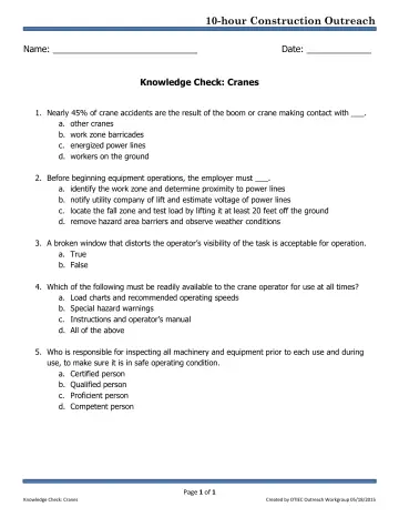
Cranes, Derricks, Hoists, Elevators, and Conveyors: Knowledge Check (OSHA 10-Hour Construction Outreach)
Student knowledge-check quiz that accompanies the OSHA cranes, derricks, hoists, elevators, and conveyors outreach deck.