Advance Rigging Principles
In-depth rigging principles course from the National Association of Tower Erectors; long and advanced, so choose slides selectively.
Slide text
· 150 slides · by National Association of Tower Erectors
The words on each slide as the author wrote them, read from the file by software so they can be searched. Layout, pictures and tables are not shown here: the slides above and the download are the original.
- Slide 1
ADVANCED RIGGING PRINCIPLES
- Hoisting Applications Using Synthetic Rope
- U.S. Department of Labor - OSHA
- Susan Harwood Grant
- SH-05018-SH8
- Slide 2
Acknowledgement
- This material was produced under a 2018 Susan Harwood Training Grant (SH-05018-SH8) from the Occupational Safety and Health Administration (OSHA), U.S. Department of Labor. It does not necessarily reflect the views or policies of the U.S. Department of Labor, nor does mention of trade names, commercial products, or organizations imply endorsement by the U.S. Government.
- Slide 3
Advanced Rigging Principles Course Organization
- The training is organized into six sections. The following sections and topics are covered in this training:
- Section 1: Introduction to OSHA
- Section 2: State of the Industry
- Section 3: Primary Regulations, Codes, Standards, and Policies
- Section 4: Synthetic Rope
- Section 5: Rigging Forces and Lift Systems
- Section 6: Hoisting Operations, Execution and Communication
- Slide 4
Pancake is to Griddle, as Hamburger is to?
- A. Lettuce
- B. Grill
- C. Bun
- D. Ketchup
- Slide 5
What is your age?
- A. 18-24
- B. 25-34
- C. 35-44
- D. 45-54
- E. 55-64
- F. 65 and up
- Slide 6
What is the size of your employer?
- A. I don’t know
- B. 2-10 employees
- C. 11- 50 employees
- D. 51 - 100 employees
- E. More than 150 employees
- Slide 7
Does your company directly perform on-site construction?
- A. Yes
- B. No
- Slide 8
Do you create rigging plans?
- A. Yes
- B. No
- Slide 9
What primary sector do you service?
- A. Wireless
- B. Broadcast
- C. Wireless and Broadcast
- D. Utilities
- E. Public Safety
- Slide 10
What is your primary responsibility for construction activities?
- A. Office support
- B. Field tech
- C. Safety officer
- D. Not directly involved
- Slide 11
Section 1
- Introduction to OSHA
- Slide 12
Topics
- Introduction to OSHA
- Importance of OSHA
- Responsibilities of the employer under OSHA
- Employee rights under OSHA
- Slide 13
About OSHA
- On December 29, 1970, President Nixon signed the Occupational Safety and Health Act of 1970 (OSH Act) into law. The OSH Act created the Occupational Safety and Health Administration (OSHA) to assure safe and healthful working conditions for working men and women by setting and enforcing standards and by providing training, outreach, education and assistance.
- Slide 14
What Does OSHA Do?
- Works with employers and employees to reduce workplace hazards through partnerships and alliances;
- Introduces new or improves upon existing safety and health programs;
- Utilizes consensuses standards through an agreement with ANSI;
- Educates on safety and health rules that are designed to protect workers;
- Enforces the rules through inspection and citations;
- Monitors job-related injuries and illnesses through electronic records and reporting;
- Conducts a variety of inspections to include: accidents, fatalities, complaints and programmed inspections.
- Slide 15
Workers Have the Right To:
- Safe and healthful working conditions;
- File a confidential complaint with OSHA to have their workplace inspected;
- Review records of work-related injuries and illnesses;
- Receive training regarding the OSHA standards that apply to their workplace;
- Report any injury or illness without retaliation or discrimination;
- Obtain copies of test results done to find hazards in the workplace; and
- Obtain copies of their medical records.
- Source: OSHA 3021-09R 2011, www.osha.gov/workers.html
- Slide 16
Employers Must:
- Provide a workplace free from recognized hazards and comply with standards, rules and regulations issued under the OSHA Act;
- Eliminate or reduce hazards by making feasible changes in working conditions;
- Not discriminate against employees who exercise their rights under the Act;
- Inform employees of hazards through training, labels, alarms, etc.;
- Train employees in a language/vocabulary employees can understand; and
- Keep accurate records of work-related injuries and illnesses.
- Source: OSHA 3021-09R 2011, www.osha.gov/workers.html
- Slide 17
OSHA Whistleblower Protection
- Visit www.osha.gov/workers.html or call 800- 321-OSHA
- Be prepared to provide specific details regarding your company and the type of hazard or discrimination being reported
- Keep a confidential record of all details
- Once a complaint is filed or reported, an investigation is normally warranted (see criteria on website)
- Source: OSHA 3021-09R 2011, www.osha.gov/workers.html
- Slide 18
Section 1 Review Questions
- Slide 19
- OSHA’s Whistleblower statutes are design to provide employees the freedom to report violations and protect employees from the following acts of retribution?
- A. Being blacklisted
- B. Demotion
- C. Being denied promotion or overtime
- D. Pay reduction
- E. All the above
- Slide 20
Employees can report hazards and violations to OSHA through which mediums?
- A. By Phone: 800-321-OSHA
- B. By Website: osha.gov/workers.html
- C. All the above
- D. None of the above
- Slide 21
Section 2
- State of the Industry
- Slide 22
Topics
- Industry Statistics
- Incident Review
- Rigging Failures and Near Misses
- Slide 23
Industry Fatality Statistics
- Year
- Fatalities
- 2003
- 2004
- 2005
- 2006
- 2007
- 2008
- 2009
- 2010
- 2011
- 2012
- 2013
- 2014
- 2015
- 2016
- 2017
- 2018
- Total Fatalities
- 15 11 7 19 11 12 5 7 7 1 14 10 4 7 8
- Slide 24
CTIA – The Wireless Association
- 2018 Wireless Snapshot
- Over 15 trillion MB carried over U.S. wireless networks last year, which is another annual record
- A record 323,448 cell sites were in operation at the end of 2017.
- CTIA indicates that today’s average download speed of 22.69 Mbps is a 60% increase from 2014
- Source: 2018 CTIA State of Wireless Report: https://api.ctia.org/wp-content/uploads/2018/07/CTIA_State-of-Wireless-2018_0710.pdf
- Slide 25
Trends and Statistics
- Sample of 35
- Reported
- Rigging
- Incidents
- 2016 – 11
- 2017 – 12
- 2018 - 13
- Reported Rigging Incidents - Technical Root Cause
- Load Rope Condition
- Excessive Rigging Forces
- Capstan Utilization
- Improper Rigging Equipment
- Slings
- Gross Load Transfer
- Other
- Slide 26
Incident #1
- Slide 27
Incident #2
- Slide 28
Incident #3
- Slide 29
Incident #4
- Slide 30
Incident #5
- Slide 31
Trends and Statistics
- Reported Rigging Incidents Per
- SOW
- Sample of 35 Reported Rigging
- Incidents
- L&A
- Structural
- Mods
- 2016
- 2017
- 2018
- 2016
- 2017
- 2018
- Tower Modification Construction
- Antenna & Line Construction
- Slide 32
Trends and Statistics
- Antenna & Line Construction:
- Approximately 25,000 jobs were sampled for incidents each year
- 12 reported L&A Incidents for 2018 sample
- Tower Modification Construction:
- Approximately 2,500 jobs were sampled for incidents each year
- 1 reported Structural Modification Incident for 2018 sample
- Reported rigging incidents rates
- 1 out of 2,083 jobs
- Reported rigging incidents rates 1 out of 2,500 jobs
- Slide 33
Impacts to the Industry
- Tower Owners
- Consumer
- Regulatory
- Public
- Carriers
- Media
- Sub-
- Contractor
- General Contractor
- Landowner
- Slide 34
Section 3
- Primary Regulations, Codes, Standards and Policies
- Slide 35
Topics
- Primary Regulations, Codes, Standards and Policies
- Telecommunications Industry Standards
- Roles and Responsibilities
- A10.48 Construction Classes
- Communications
- Slide 36
Regulations, Codes, Standards and Policies
- Federal Regulations for General Industry and Construction establish laws set forth by the DOL and represent minimum requirements which must be satisfied to safeguard employee health, safety and welfare.
- State Regulations may build on Federal Regulations to establish more stringent requirements, but may not set forth requirements below those established at a Federal level.
- Building Codes adopted and enforced by one or more government entity and contain collection of evolving standards by direct or indirect reference.
- ANSI Standards represent voluntary guidelines to a given trade or industry developed by a consensus of committee members representing private stakeholders, trade organizations, and professional societies in compliance with the ANSI rules.
- Consensus Standards represent voluntary guidelines to a given trade or industry developed by a consensus of committee members representing private stakeholders, trade organizations, and professional societies.
- Consensus standards can be enforceable when referenced/recognized by Regulations or Codes
- Owner/Company/Customer Policies
- Slide 37
Rigging Equipment Standards
- Standard Rigging Equipment Used For Lifting and Load Handling Purposes Shall be Specifically Certified for Such Applications in Accordance With Applicable ANSI/ASME B30 Standards
- ASME B30.9: Slings
- ASME B30.10: Hooks
- ASME B30.26: Shackles, Links, Rings, Rigging Blocks, and Load Indicating Devices
- Slide 38
Applicable ANSI Standards
- ANSI/ASSE A10.48 – Criteria for Safety Practices with the Construction, Demolition, Modification and Maintenance of communications structures.
- ANSI/TIA 222 – Structural Standard for Antenna Supporting Structures, Antennas and Small Wind Turbine Support Structures
- ANSI/TIA 322 – Loading Analysis, and Design Criteria Related to the Installation, Alteration and Maintenance of Communication Structures.
- Note: ANSI/TIA-222-H directly references 322/A10.48 (i.e. 2018 IBC consequently indirectly ref 322/A10.48)
- Slide 39
Rope Standards
- Cordage Institute CI 2001-04 – Fiber Rope Inspection and Retirement Criteria
- Cordage Institute is an international association of rope, twine, and related manufacturers, their suppliers, and affiliated industries.
- This is a consensus standard
- Slide 40
A10.48 Standard
- Climber Connection Video
- https://natehome.com/safety-education/climber-connection/
- Slide 41
Section 3 Review Questions
- Slide 42
- Which of the following is the most industry specific standard for safe work practices on a communication structure?
- A. ANSI/TIA 322
- B. ANSI/ASME B30.26
- C. OSHA 29 CFR 1926
- D. ANSI/ASSE A10.48
- Slide 43
Who is responsible for the onsite execution of a rigging plan per ANSI A10.48?
- A. Tower Technician II
- B. Qualified Person
- C. Competent Rigger
- D. Qualified Engineer
- Slide 44
Which construction class always requires engagement of a qualified engineer?
- A. Class IV
- B. Class I
- C. Class III
- D. Class II
- Slide 45
Which standard contains inspection and retirement criteria for synthetic ropes?
- A. ANSI/ASME B30.9
- B. Cordage Institute 2001-04
- C. ANSI/TIA – 222
- D. ANSI/ASSE A10.48
- Slide 46
Section 4
- Synthetic Rope
- Slide 47
Topics
- Having knowledge of all equipment in your lifting plan is critical.
- Synthetic Rope
- Blocks, Slings, and Shackles
- Selection/Marking, Use, and Maintenance/Inspection
- System Compatibility
- Slide 48
Kernmantle Rope
- Is ideal for use in rescue, lifelines, ascent/decent rope access work
- Highest Strength/Weight Ratio
- The most frequent kernmantle rope diameters used in telecom is 12mm (1/2”)
- Slide 49
Double Braid Rope
- Most common type of rope used for hoisting is Double Braid
- Double Braid is a braided core surrounded by a braided sheath
- Both braids share the load equally
- Ideal for load rope
- Slide 50
3 Strand Rope
- Most common type of rope used for chase rope
- 5/8” is sometimes used as a backup lifeline.
- Remember that life safety ropes can never be used for material handling.
- Allows users to take their primary rope out of service for proper storage and inspection, and easily get back to operation
- Slide 51
Know Your Rope
- Knowing your rope specifications is critical.
- Type of Rope
- Rope Manufacturer
- Date of Manufacturing
- MBS
- Where can this information be found?
- Slide 52
Terms for Rigging
- ABS
- Average Breaking Strength
- MBS
- Minimum Breaking Strength
- SWL
- Being Phased Out
- WLL
- Working Load Limit
- The minimum breaking load of a component divided by an appropriate factor of safety giving a maximum load that can be lifted or be carried.
- (WLL) For Ropes, is 10% of the (MBS) minimum breaking strength
- FS
- 10:1
- Factor of Safety
- Slide 53
Diameter & MBS
- Breaking Strength of Synthetic Rope must be known
- Below is an example of one manufacturer’s Double Braid
- Each manufacturer’s ratings are different, as different constructions and materials are used.
- Example:
- Slide 54
Calculating WLL
- Breaking Strength ÷ Factor of Safety
- You have a ½” Double Braid Polyester rope that has a MBS of 11,000 pounds.
- What is the WLL that can be safely lifted?
- Slide 55
Calculating WLL
- Breaking Strength ÷ Factor of Safety
- You have a ½” Double Braid Polyester rope that has a MBS of 11,000 pounds.
- Answer: 11,000 (MBS) ÷ 10 = 1,100 lbs.
- Slide 56
Knots & Terminations
- ~50-80%
- ~90%
- ~98%
- Slide 57
Cordage Institute
- Cordage Institute is an international association of rope manufacturers, nearly 100 years old, that creates uniform rope standards
- CI 2001-04
- Fiber Rope Inspection &
- Retirement Criteria
- Slide 58
CI 2001-04 Guidelines
- Of particular interest to our industry is Section 4
- Inspection & Retirement Programs
- The following sections present the requirements for an effective inspection and retirement program.
- Slide 59
CI 2001-04 Guidelines
- 4.1.1 The user is responsible to establish a program for inspection and retirement that considers conditions of use and degree of risk for the particular application.
- A program should include:
- Assignment of supervisory responsibility. The user should assign an individual responsible for establishing the program, for training and qualifying inspectors and preserving records.
- Written procedures
- Training
- Record keeping
- Establishment of retirement criteria for each application.
- Schedule for inspections.
- Slide 60
CI 2001-04 Requirements
- 4.1.2 Ropes that secure or control valuable assets or whose failure would cause serious damage, pollution, or threat to life warrant more scrutiny than ropes in non-critical use. If a fiber rope is used in a highly demanding application, with potentially critical risks, the advice of a qualified person should be obtained when developing the specific inspection and retirement program.
- Slide 61
CI 2001-04 Requirements
- 4.1.3 The user should continue to revise and refine the program based on experience.
- Slide 62
Rope Inspection Log
- CI 2001-4.3
- “An important tool for rope evaluation is a log. This will include data on the type of rope, time in service and description of intended use. The details of every inspection should be entered in the log as to date, location and conclusions. The log should include a regular inspection schedule.”
- CI 2001-5.1.1
- During the inspection, identify the rope with a tag.
- Shrink tube is an inexpensive solution
- Slide 63
Sample Rope Log
- Slide 64
Rope Inspection
- Section 6 outlines common causes of rope damage and describes their effects. These include:
- Excessive Tension / Shock Loading
- Knots
- Cyclic Tension Wear
- Creep
- Nicks, cuts, and abrasion damage
- Sunlight Degradation
- Pulled Strands and Yarns
- Chemical & Heat Degradation
- Flex Fatigue
- Dirt & Grit
- Slide 65
Rope Inspection
- Take note of factors such as load history, bending radius, abrasion, chemical exposure.
- Inspecting your rope should be a continuous process of observation, during, and after each use.
- Look and feel along every inch of rope length inspecting for cut strands, compression, pulled strands, melted or glazed fibers, discoloration, degradation, inconsistent diameter and abrasion .
- Signs of these may indicate possible loss of strength.
- Slide 66
Rope Inspections
- Can this rope be used safely?
- Glossy/Glazed: Glossy or glazed areas in rope indicate that it has been exposed to heat damage or compression. Remove affected section. If not possible, retire rope.
- Slide 67
Rope Inspections
- Can this rope be used safely?
- Inconsistent Diameter: Look for flat areas, bumps, or lumps in the rope. This can be a sign of core or internal damage from overloading or shock loads. Remove affected section. If not possible, retire rope.
- Slide 68
Rope Inspections
- Can this rope be used safely?
- Wear: Any kind of burns, cuts, nicks, broken yarns, or excess wear (50% on double braid) on the sheath is also a sign that the rope needs to be removed from service.
- Slide 69
Rope Inspections
- Can this rope be used safely?
- Discoloration: Ropes get dirty, but if the discoloration is from excess sun exposure or chemicals, the rope should be removed from service. Determining if discoloration is from dirt and grime or something more like sun exposure or chemicals is much easier if you regularly clean your rope.
- Slide 70
Rope Care & Maintenance
- Washing
- Dirt and grease causes internal fiber abrasion, and shortens its life. Wash by hand in a bath with non-bleaching, non-detergent soap.
- Drying
- Dry your rope in a clean, dry area out of the sun.
- Recording
- Record the cleaning in your rope log.
- Slide 71
Rope Storage
- Storage
- Store your rope in a cool, clean, dark, dry environment.
- Excess humidity will damage your rope.
- Slide 72
Other Components
- ANSI B30 Compliant Blocks, Shackles, Slings
- Slide 73
Blocks
- ASME B30.26
- Safety Factor SF 4:1
- Only use blocks designed to be used with synthetic rope
- Blocks must have sufficient ductility to permanently deform before losing the ability to support the load
- Slide 74
Blocks
- Block sheave and block groove must be compatible to rope size
- Slide 75
DO NOT USE
- Slide 76
Block Marking Requirements
- Blocks must have the following durable markings
- Name or trademark of manufacturer
- Rated load (WLL)
- Rope size capacity
- Identification must be maintained by the user so as to be legible throughout the life of the block
- Slide 77
Block Inspections
- Inspections should be performed by a designated person
- Any perceived deficiencies must be examined by a qualified person to determine whether they constitute a hazard
- A visual inspection shall be performed each shift before the block is used
- Periodic inspection by a qualified person with a frequency not less than once per year, consult ASME B30.26-5.8.4 in order to determine the frequency necessary for your application
- Slide 78
Block Retirement
- Rigging blocks shall be removed from service if conditions such as those included in, but not limited to, the list below are present
- Missing/illegible identification
- Misalignment or wobble in sheaves
- Excessive sheave groove wear
- Loose more missing hardware
- Indications of heat damage including weld patter or arc strikes
- Excessive pitting or corrosion
- Bent, cracked, twisted, distorted, stretched, elongated, or broken load bearing components
- A 10% reduction in catalog dimension at any point
- Evidence of unauthorized modifications
- Visible damage that cause doubt as to the continued use of the block
- Slide 79
Sling Marking Requirements
- Per ASME B30.9, each synthetic web sling shall have:
- Tag must be present
- Tag must identify
- Manufacturer
- Chocked, vertical and basket configuration
- Sling Material
- Date
- Serial Number
- Slide 80
ASME B30.9 Sling Inspections
- Slide 81
Sling Inspections
- Can these slings be used safely?
- Slide 82
Sling Inspections
- Can these slings be used safely?
- Slide 83
Sling Inspections
- Can these slings be used safely?
- Slide 84
Inspection Requirements
- Three types of inspection:
- Initial Inspection- When you first receive it
- Frequent Inspection- Each time used, Prior to use and prior to change in application
- Periodic Inspection- Annual inspection
- Inspect it by pulling the sling through your hand and looking for visible signs.
- If you feel something, or see something that causes doubt, REMOVE FROM SERVICE
- Slide 85
Endless Synthetic Sling Chart
- The outer jacket of the sling is for protection of the material that is actually providing the sling’s capacity
- Slide 86
Shackle Marking Requirements
- Per ASME B30.26, each shackle shall have:
- Safety Factor SF 5:1
- Shackle must have sufficient ductility to permanently deform before losing the ability to support the load
- Markings on Shackle Body
- Name or trademark of manufacturer
- Rated load
- Size
- Marking on Shackle Pin
- Grade, material type, or load rating
- Slide 87
Shackle Inspections
- Inspections should be performed by a designated person
- Any perceived deficiencies must be examined by a qualified person to determine whether they constitute a hazard
- A visual inspection shall be performed each shift before the shackle is used
- Periodic inspection by a qualified person with a frequency not less than once per year, consult ASME B30.26-1.8.4 in order to determine the frequency necessary for your application
- Slide 88
Shackle Retirement
- Shackles shall be removed from service if conditions such as those included in, but not limited to, the list below are present
- Missing/illegible identification
- Indications of heat damage, including weld splatter
- Excessive pitting or corrosion
- Bent, twisted, distorted, stretched, elongated, cracked or broken load bearing components
- Excessive nicks or gouges
- A 10% reduction in catalog dimension at any point
- Incomplete pin engagement
- Excessive thread damage
- Evidence of modification
- Visible damage that cause doubt as to the continued use of the shackle
- Slide 89
System Compatibility
- Your system is only as strong as its weakest link
- What parts you need to consider?
- Rope Size/Manufacturer
- Rope Termination
- Rope Care/Maintenance
- Block for proper use
- Block Size & Construction
- Appropriate Slings & Shackles
- Etc.
- Slide 90
Section 4 Review Questions
- Slide 91
What information must be durably marked on the rigging block?
- A. Working load limit
- B. Rope Length
- C. Date of manufacture
- D. Part number
- Slide 92
What is the WLL of a synthetic rope with a MBS of 11,000 lbs.?
- A. 2,200 lbs.
- B. 5,500 lbs.
- C. 11,000 lbs.
- D. 1,100 lbs.
- Slide 93
The best place to store rope not in use is?
- A. The bed of a truck
- B. A Moist location
- C. Clean, dark, dry location
- D. The ground
- Slide 94
- The standards group which has developed a standard for the inspection and retirement of rope is?
- A. American Society of Mechanical Engineers
- B. Cordage Institute
- C. TIA (Telecommunications Industry Association)
- D. OSHA
- Slide 95
It is important to regularly clean your rope because?
- A. A clean rope is a good rope
- B. It protects it from the sun
- C. Prevents rope tangling
- D. Dirt causes internal friction and weakens rope
- Slide 96
What information should be included in a rope inspection log?
- A. Date of Manufacturing
- B. Storage Method
- C. Country of Manufacturing
- D. Temperature
- Slide 97
What is the weakest link in this hoisting system?
- A. 1,000 lbs. Capstan Hoist
- B. 3/8” Double Braid Rope with 5,000 MBS
- C. Block (2 tons)
- D. ½” Shackle (2 tons)
- Slide 98
Section 5
- Rigging Forces and Lift Systems
- Slide 99
Topics
- Typical Lift Configurations
- Sling Forces
- Block Forces
- Line Forces
- Worked Examples
- Slide 100
Calculation Notes
- Calculated rigging forces provided in this presentation are intended for synthetic rope hoisting operations using typical 1,000 lbs. capstan hoists
- Calculations are based upon the following assumptions:
- Block and Sling Forces assume constant line tension through the system (no friction and no reduction for fall line weight)
- Line pull demands seen at hoist include compensation for fall line weight and friction in the reeved sheave assemblies
- NOTE: Additional considerations may be required for more complex lifting systems including, but not limited to, line parts of 3 or more, 3 or more reeved sheaves, and/or gin pole applications.
- Slide 101
Typical Lift Configurations
- Four Standard Lifting Block Arrangements:
- 1) Top Block Only With Straight Tag
- 2) Top And Heel Blocks With Straight Tag
- 3) Integrated Trolley (aka Self-Trolley)
- 4) Dedicated Trolley
- Slide 102
Typical Lift Configurations
- Straight Tag With Top Block Only:
- PROS:
- Simple system incorporating only one block
- Easy to setup
- CONS:
- Tag line must be kept away from load line
- Load line can act as a visual obstruction
- Difficult for hoist operator to visually identify clearance issues during hoisting
- Applies vertical load to hoisting unit (must ensure mounting unit is rated for vertical loading)
- Less overall load control
- Increased tendency for shock/impact loads
- Increased tendency for developing high imposed rigging forces due to tag forces
- Slide 103
Typical Lift Configurations
- Straight Tag With Top and Heel Blocks:
- PROS:
- Provides added control to lead line and removes visual obstruction
- Allows more diverse hoist setup options
- CONS:
- More difficult to employ on towers with multiple obstructions/equipment below working elevations (may require reeving through obstructions)
- Increased tendency for shock/impact loads
- Increased tendency for developing high imposed rigging forces due to tag forces
- Slide 104
Typical Lift Configurations
- Integrated Trolley (aka Self-Trolley):
- PROS:
- Simple system incorporating only one block Easy to setup
- Uses single line for both lifting and control Provides good load control
- Predictable rigging forces in load line
- CONS:
- Limits hoist setup locations
- Clear distance from structure/obstructions cannot be easily manipulated during lift (issue for obstructions and multiple work elevations)
- Applies vertical load to hoisting unit (must ensure mounting unit is rated for vertical loading)
- Load angle and load line clear distance reduces as load is raised, and is significantly less during lowering operations due to sheave friction
- Slide 105
Typical Lift Configurations
- Dedicated Trolley:
- PROS:
- Provides added control to lead line and removes visual obstruction
- Allows diverse hoist setup options
- Superior load control
- Tag induces least force onto load
- Predictable rigging forces in load line
- CONS:
- Requires additional rigging attachments which requires additional crew members to properly monitor
- More difficult to employ on towers with multiple obstructions/equipment below working elevations (may require reeving through obstructions)
- Slide 106
Sling Forces
- To determine Sling Force, must know:
- 1) Applied Load
- 2) Sling Hitch Configuration
- 3) Sling Angle
- Slide 107
Sling Forces
- Types of Hitches:
- Vertical Hitch
- Choker Hitch
- Basket Hitch
- Bridle Hitch
- Multiple Slings
- Slide 108
Sling Forces
- Vertical and Choker Hitches:
- APPLIED LOAD
- ANCHORED
- END
- ANCHORED
- END
- Slide 109
Sling Forces
- Symmetrically Loaded Basket Hitches & 2-Leg Bridle Hitches:
- APPLIED LOAD
- ANCHORED
- END
- ANCHORED
- ENDS
- Slide 110
Sling Forces
- Sling Angle:
- Acute angle between sling leg and the plane perpendicular to the direction of the applied load
- For lifting applications, angle measured from horizontal to sling leg while accounting for incline in the rendered plane
- Slide 111
Sling Forces
- CRITICAL POINT:
- At 30° Sling Angle, Load
- Factor = 2.0
- Exponential Relationship
- Linear
- Relationship
- Slide 112
Sling Forces
- Sling Angle Factors:
- SLING
- SLING
- ANGLE FACTOR
- ANGLE, ϴ
- AF
- ANGLE, ϴ
- AF
- 90°
- 1.000
- 55°
- 1.221
- 85°
- 1.004
- 50°
- 1.305
- 80°
- 1.015
- 45°
- 1.414
- 75°
- 1.035
- 40°
- 1.556
- 70°
- 1.064
- 35°
- 1.743
- 65°
- 1.103
- 30°
- 2.000
- 60°
- 1.155
- DO NOT SET BELOW 30°
- Critical Angles To Remember:
- 1) 60°: Recommended Min Angle per ANSI/ASSE A10.48
- 2) 45°: Min Angle per ANSI/ASSE A10.48 ~ Below 45° Requires Special Approval
- 3) 30°: Min Angle per ASME B30.9 ~ Below 30° Requires Special Attention
- Slide 113
Block Forces
- To determine Block Force, must know:
- 1) Line Tension
- 2) Block Included Angle
- Slide 114
Block Forces
- Included Angle, ϴ:
- Angle formed between legs of line e.g. Straight vertical lift ~ ϴ=0°
- BLOCK
- FORCE, F
- Angle Factor, AF:
- Multiplication factor based on Included Angle
- INCLUDED
- ANGLE, ϴ
- TENSION
- IN LINE, P
- TENSION
- IN LINE, P
- Slide 115
Block Forces
- INCLUDED ANGLE FACTOR INCLUDED ANGLE FACTOR INCLUDED ANGLE FACTOR INCLUDED ANGLE FACTOR
- ANGLE, ϴ
- AF
- ANGLE, ϴ
- AF
- ANGLE, ϴ
- AF
- ANGLE, ϴ
- AF
- 0°
- 2.000
- 45°
- 1.848
- 90°
- 1.414
- 135°
- 0.765
- 5°
- 1.998
- 50°
- 1.813
- 95°
- 1.351
- 140°
- 0.684
- 10°
- 1.992
- 55°
- 1.774
- 100°
- 1.286
- 145°
- 0.601
- 15°
- 1.983
- 60°
- 1.732
- 105°
- 1.218
- 150°
- 0.518
- 20°
- 1.970
- 65°
- 1.687
- 110°
- 1.147
- 155°
- 0.433
- 25°
- 1.953
- 70°
- 1.638
- 115°
- 1.075
- 160°
- 0.347
- 30°
- 1.932
- 75°
- 1.587
- 120°
- 1.000
- 165°
- 0.261
- 35°
- 1.907
- 80°
- 1.532
- 125°
- 0.923
- 170°
- 0.174
- 40°
- 1.879
- 85°
- 1.475
- 130°
- 0.845
- 175°
- 0.087
- Two Key Standard Angle Factors To Remember:
- 1) Top Block Angle Factor: During lift and setting the load, ϴ min =0° AF ~ 2.0
- 2) Heel Block Angle Factor: ϴ typically ranges from 85°-95° AF ~ 1.5
- Slide 116
Line Forces
- To determine Line Forces, must know:
- 1) Gross load weight
- 2) Tag method
- 3) Number of line parts
- 4) Sheave frictional resistance
- 5) Load position and tag angles
- Slide 117
Line Forces
- Load Side
- Gross Load, WT:
- WT = Lifted Load + Rigging Weight on Load Side
- Load Line Weight
- Do not need to include fall line weight to hoist
- Fall Line (To Hoist)
- Rigging Weight
- Overhaul ball/weight, slings, shackles, etc.
- Load Weight
- Tag Line Weight
- Only include for Straight
- Tag configurations
- Slide 118
Line Forces
- Tag Method:
- Straight Tag
- Trolley Tag
- Integrated Trolley (aka Self-Trolley)
- Dedicated Trolley
- Slide 119
Line Forces
- Straight Tag:
- Tag Line force is directly transferred into the Load Line
- Increased tendency for developing excessive forces in the Load Line
- Increased tendency for shock/impact loading
- Provides simple means for controlling the load with minimal attachments
- Slide 120
Line Forces
- Trolley Tag:
- Tag Line force is NOT transferred into the Load Line
- During active lifting, the tag line actually relieves force from the load line; however, the Load Line ultimately supports the full Gross Load during the initial lift and final landing
- Predictable Load Line force
- Provides superior load control
- Requires additional attachments which must be monitored during hoisting operations
- More so for Dedicated Trolley
- Configurations
- Slide 121
Line Forces
- Number of Line Parts:
- LOA D
- 2-Part
- Fall Line (To Hoist)
- Single Part
- LOA D
- Slide 122
Line Forces
- Line Parting Principles:
- Multi-parting the line provides a mechanical advantage for hoisting operations
- 2-parting the line is most common for hoisting applications with synthetic rope
- Results in loss of load travel speed
- Increases frictional resistance of the hoisting system
- Important to consider attachment anchorage location for dead-end
- If attached to rigging block becket, the additional line tension must be added to the resulting block force
- Slide 123
(To D Line
- Line Forces
- Dead-End
- Line Parting Principles:
- System Components:
- Blocks
- Dead-End
- Parts of Line
- Dead
- ead- End)
- Stationary
- Block
- Line Retur
- Provides up to a 2:1 mechanical advantage not accounting for block angles and friction
- Actual mechanical advantage typically ranges from around 1.5-1.9:1 for most common configurations
- Fall Line (To Hoist)
- 2-Part Hoisting Configuration
- Travelling
- Block
- LOA D
- Slide 124
Line Forces
- Mechanical Advantage for Typical 2-Part Arrangements:
- Must account for bearing type and total reeved sheaves in the system Losses attributed to sheave friction results in less mechanical advantage
- TOTAL NO
- REEVED SHEAVES, S
- 2 3 4 5 6
- 2-PART MECHANICAL ADVANTAGE
- STD PLAIN BEARINGS STD BRONZE BUSHINGS STD ROLLER BEARINGS
- (K=1.09)
- (K=1.045)
- (K=1.02)
- 1.759
- 1.873
- 1.942
- 1.614
- 1.792
- 1.903
- 1.481
- 1.715
- 1.866
- 1.358
- 1.641
- 1.830
- 1.246
- 1.570
- 1.794
- Table based on common Bearing Constants, K, as specified
- NOTE:
- 1) Typical 2-Part arrangement with top and heel blocks will have a minimum of 3 reeved sheaves ~ heel block, top block, and travelling block
- 2) Each additional diverter/fairlead must be considered, and ultimately decreases the systems mechanical efficiency
- Slide 125
Line Forces
- Sheave Frictional Resistance:
- TOTAL NO
- REEVED
- SHEAVES, S
- PB 1.090 1.188 1.295 1.412 1.539 1.677 1.828 1.993 2.172 2.367
- 1-Part
- BB
- 1.045
- 1.092
- 1.141
- 1.193
- 1.246
- 1.302
- 1.361
- 1.422
- 1.486
- 1.553
- SRB 1.020 1.040 1.061 1.082 1.104 1.126 1.149 1.172 1.195 1.219
- PB 1.137 1.239 1.351 1.472 1.605 1.749 1.907 2.078 2.265
- SHEAVE FRICTION FACTOR, SFF
- NO OF LINE PARTS, N
- 2-Part
- 3-Part
- BB
- SRB
- PB
- BB
- 1.068
- 1.030
- 1.116
- 1.051
- 1.185
- 1.091
- 1.166
- 1.072
- 1.292
- 1.140
- 1.219
- 1.093
- 1.408
- 1.192
- 1.274
- 1.115
- 1.535
- 1.245
- 1.331
- 1.137
- 1.673
- 1.301
- 1.391
- 1.160
- 1.824
- 1.360
- 1.453
- 1.183
- 1.988
- 1.421
- 1.519
- 1.207
- 2.167
- 1.485
- SRB 1.040 1.061 1.082 1.104 1.126 1.149 1.172 1.195
- PB 1.235 1.346 1.467 1.599 1.743 1.900 2.071
- 4-Part
- BB
- 1.115
- 1.165
- 1.218
- 1.272
- 1.330
- 1.389
- 1.452
- SRB 1.050 1.072 1.093 1.115 1.137 1.160 1.183
- Table based on bearing constants, K, of: Plain Bearings, PB=1 .09 l Bronze Bushings, BB=1 .045 l Steel Roller Bearings, SRB=1 .02
- Slide 126
Line Forces
- Load Position and Tag Angles:
- Angles and resulting line forces CHANGE throughout the various stages of the lift based on the tag force applied to create the horizontal clear distance needed to keep the load a safe distance from the structure and other obstructions
- Must consider ENTIRE lifting operation from ground level to uppermost position to properly assess the maximum line forces created in the Load Line and Tag Line
- Slide 127
Line Forces
- RISE
- Load Position and Tag Angles:
- RUN
- (deg)
- 90°
- 89°
- 88°
- 87°
- 86°
- 85°
- 84°
- 83°
- 82°
- 81°
- 80°
- 79°
- 78°
- 77°
- 76°
- RISE RUN 0.02 0.03 0.05 0.07 0.09 0.11 0.12 0.14 0.16 0.18 0.19 0.21 0.23 0.25
- (deg)
- 0°
- 1°
- 2°
- 3°
- 4°
- 5°
- 6°
- 7°
- 8°
- 9°
- 10°
- 11°
- 12°
- 13°
- 14°
- (deg)
- 75°
- 74°
- 73°
- 72°
- 71°
- 70°
- 69°
- 68°
- 67°
- 66°
- 65°
- 64°
- 63°
- 62°
- 61°
- RISE RUN 0.27 0.29 0.31 0.32 0.34 0.36 0.38 0.40 0.42 0.45 0.47 0.49 0.51 0.53 0.55
- (deg)
- 15°
- 16°
- 17°
- 18°
- 19°
- 20°
- 21°
- 22°
- 23°
- 24°
- 25°
- 26°
- 27°
- 28°
- 29°
- (deg)
- 60°
- 59°
- 58°
- 57°
- 56°
- 55°
- 54°
- 53°
- 52°
- 51°
- 50°
- 49°
- 48°
- 47°
- 46°
- RISE RUN 0.58 0.60 0.62 0.65 0.67 0.70 0.73 0.75 0.78 0.81 0.84 0.87 0.90 0.93 0.97
- (deg)
- 30°
- 31°
- 32°
- 33°
- 34°
- 35°
- 36°
- 37°
- 38°
- 39°
- 40°
- 41°
- 42°
- 43°
- 44°
- (deg)
- 45°
- 44°
- 43°
- 42°
- 41°
- 40°
- 39°
- 38°
- 37°
- 36°
- 35°
- 34°
- 33°
- 32°
- 31°
- RISE RUN 1.00 1.04 1.07 1.11 1.15 1.19 1.23 1.28 1.33 1.38 1.43 1.48 1.54 1.60 1.66
- (deg)
- 45°
- 46°
- 47°
- 48°
- 49°
- 50°
- 51°
- 52°
- 53°
- 54°
- 55°
- 56°
- 57°
- 58°
- 59°
- (deg)
- 30°
- 29°
- 28°
- 27°
- 26°
- 25°
- 24°
- 23°
- 22°
- 21°
- 20°
- 19°
- 18°
- 17°
- 16°
- RISE RUN 1.73 1.80 1.88 1.96 2.05 2.14 2.25 2.36 2.48 2.61 2.75 2.90 3.08 3.27 3.49
- (deg)
- 60°
- 61°
- 62°
- 63°
- 64°
- 65°
- 66°
- 67°
- 68°
- 69°
- 70°
- 71°
- 72°
- 73°
- 74°
- (deg)
- 15°
- 14°
- 13°
- 12°
- 11°
- 10°
- 9°
- 8°
- 7°
- 6°
- 5°
- 4°
- 3°
- 2°
- 1°
- RISE RUN 3.73 4.01 4.33 4.70 5.14 5.67 6.31 7.12 8.14 9.51 11.43 14.30 19.08 28.64 57.29
- (deg)
- 75°
- 76°
- 77°
- 78°
- 79°
- 80°
- 81°
- 82°
- 83°
- 84°
- 85°
- 86°
- 87°
- 88°
- 89°
- Slide 128
Line Forces
- At minimum, resulting angles must be considered at the following lift positions:
- 1) Ground Level
- 2) Any Obstruction(s)
- 3) Uppermost Lift Position
- For most operations, it is best practice to base your line force calculations using the Maximum Load Position Angle and Maximum Tag Angle
- Slide 129
Headroom
- Line Forces
- NOTE:
- Standoff distance at 5° equals a RISE/RUN ratio of 11.4
- Standoff distance at 10° equals a RISE/RUN ratio of 5.7
- Angle between true vertical and the rendered Load Line
- Best practice is to limit to 5° or less
- Once you exceed 10° on Straight Tag configurations, Load Line force can become excessive
- “RISE”
- Load Position Angle, Ø:
- “RUN”
- Standoff
- Slide 130
Line Forces
- Always Determine Maximum Load Position Angle, Ø:
- At Ground Level
- At Tower Obstruction
- At Top Position
- Slide 131
Line Forces
- Tag Angle for Straight Tag Configurations, α:
- Angle between horizontal and the rendered Tag Line
- NOTE:
- “RISE”
- Maximum Tag Angle occurs at uppermost position of lift
- “RUN”
- Slide 132
Line Forces
- “RISE”
- Must identify BOTH angles to determine resulting Tag Line Force
- T : Angle between true vertical and the rendered Tag Line on tower side of trolley block α T : Angle between horizontal and the rendered Tag Line on opposite side of trolley block
- “RISE”
- “RUN”
- “RUN”
- Slide 133
Load Line Multiplier
- Line Forces
- CRITICAL POINT:
- 10° Load Angle & 70° Tag Angle, Load Factor = 2.0
- “10/70” Rule
- Exponential Relationship
- Linear
- Relationship
- Maximum Tag Angle
- Slide 134
Line Forces
- Slide 135
Line Forces
- Line Forces at Load:
- Where:
- P = Load Line Force at Load
- T = Tag Line Force at Load
- WT = Gross Load Weight
- PM = Load Line Multiplier (Refer to Handbook)
- *NOTE: For Trolley Tag Arrangements, Set PM=1.0 for Uppermost Position
- TM = Tag Line Multiplier (Refer to Handbook) N P = Number of Line Parts in Load Line
- N T = Number of Line Parts in Tag Line
- Slide 136
Line Forces
- Load Line Pull at Hoist:
- Where:
- P H = Load Line Pull at Hoist
- P = Load Line Force at Load
- FLW = Fall Line Weight
- SFF = Sheave Friction Factor
- AM = Additional Multipliers (i.e. Additional Angle/Safety Factors, Etc.)
- Slide 137
Line Forces
- Trolley Block Force:
- ;Conservative Estimate
- Trolley Block
- Where:
- T = Tag Line Force at Load
- (or Load Line Force at Load, P, for Integrated Trolley Systems)
- Slide 138
Worked Examples
- Refer to the loose Straight Tag Example and forms provided in your Handbook
- Turn to Page 98 of your Handbook to locate the Tables we’ll be using for this example
- Slide 139
Straight Tag Example
- Refer to Loose Handouts in the back of your Handbook for the STRAIGHT TAG EXAMPLE:
- Slide 140
Straight Tag Example
- Slide 141
Straight Tag Example
- STEP 1) Determine the Gross Load Weight
- Slide 142
Straight Tag Example
- STEP 1) Determine the Gross Load Weight
- 400 lbs
- 20 lbs
- 20 lbs
- 25 lbs
- 465 lbs
- 20 lbs
- 130 ft
- Load Line Weight:
- 145 ft x 0.14 plf = Approx. 20 lbs
- Tag Line Weight:
- GROSS LOAD WEIGHT:
- 400 + 20 + 20 + 25 = 465 lbs
- Fall Line Weight, FLW:
- Slide 143
Straight Tag Example
- STEP 2) Determine the Maximum Load Position and Tag Angles
- Slide 144
Straight Tag Example
- STEP 2) Determine the Maximum Load Position and Tag Angles
- Slide 145
Straight Tag Example
- STEP 2) Determine the Maximum Load Position and Tag Angles
- “B”
- “A”
- Slide 146
Straight Tag Example
- STEP 2) Determine the Maximum Load Position and Tag Angles
- 12 ft 2.5 ft 4.80
- Slide 147
Straight Tag Example
- STEP 2) Determine the Maximum Load Position and Tag Angles
- Slide 148
Straight Tag Example
- STEP 2) Determine the Maximum Load Position and Tag Angles
- 12 ft 2.5 ft 4.80 12
- Slide 149
Straight Tag Example
- STEP 2) Determine the Maximum Load Position and Tag Angles
- “C”
- “D”
- Slide 150
Straight Tag Example
- STEP 2) Determine the Maximum Load Position and Tag Angles
- 12 ft 2.5 ft 4.80 12 128 ft 47 ft 2.72
More on Cranes

Cranes, Derricks, Hoists, Elevators, and Conveyors (OSHA 10-Hour Construction Outreach)
OSHA's own 10-hour Construction Outreach deck on crane hazards: power lines, load charts, rigging, signal persons and inspections (2015 edition).
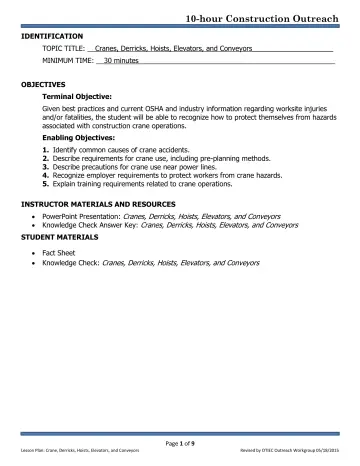
Cranes, Derricks, Hoists, Elevators, and Conveyors: Lesson Plan (OSHA 10-Hour Construction Outreach)
Instructor lesson plan with objectives, timing and teaching procedures for the OSHA cranes, derricks, hoists, elevators, and conveyors outreach deck.
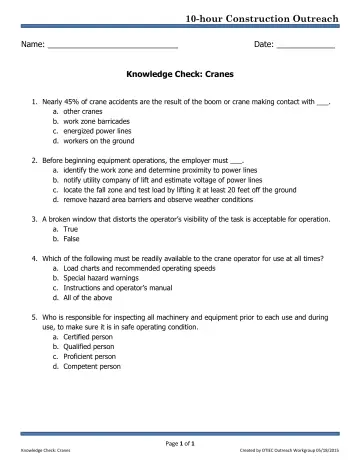
Cranes, Derricks, Hoists, Elevators, and Conveyors: Knowledge Check (OSHA 10-Hour Construction Outreach)
Student knowledge-check quiz that accompanies the OSHA cranes, derricks, hoists, elevators, and conveyors outreach deck.